20% Bonus On your First Rechargeclose

Méthodes couramment utilisées pour le dépliage UV dans 3ds Max

Dans cet article, Fox Renderfarm, l’un des principaux fournisseurs de services de rendu cloud et ferme de rendu dans l’industrie de la 3D, vous présente quelques méthodes couramment utilisées pour le dépliage UV dans 3ds Max. Bien que la version installée de 3ds Max soit assez ancienne (2014), cela n’a pas d’impact majeur sur les fonctionnalités de dépliage UV.

Pour modifier les UVW, il suffit d’aller dans : Panneau Modifier > Dépliage UVW > Ouvrir l’Éditeur UV

edit UVW

1. Barre d’outils principale

La barre d’outils contient des commandes permettant de manipuler les sous-objets de texture dans la vue ainsi que des commandes pour définir différentes options.

barre d’outils

Miroir et Retournement

De haut en bas, il s'agit de : miroir horizontal, miroir vertical, retournement horizontal, retournement vertical.

Miroir et Retournement

Cependant, la différence entre les deux est que le retournement peut entraîner la séparation du modèle le long du bord sélectionné.

le retournement peut entraîner la séparation du modèle

Mais le modèle en miroir reste une entité unique.

le modèle en miroir reste une entité unique

Option de déballage - maille

Si le modèle doit être importé dans un moteur, par exemple pour créer une animation matérielle de l'interface utilisateur, la grille est un point important à prendre en compte. L'ordre et la proportion de la disposition des UV sont relativement importants.

En cliquant sur Ouvrir, l’interface des options de dépliage s’affichera.

En cliquant sur Ouvrir, l’interface des options de dépliage s’affichera.

En cochant Afficher la grille, la plage normale est de 0 à 1, ce qui signifie que chaque case de la grille représente 0,1.

Cocher la case Afficher la grille

La taille de la grille peut être utilisée pour ajuster la fréquence de la grille.

La taille de la grille peut être utilisée pour ajuster la fréquence de la grille.

2. Barre d’outils inférieure

Les deux barres d’outils inférieures incluent :

La sélection et la transformation des sous-objets

La sélection et la transformation des sous-objets

L’activation de l’affichage de la barre d’attributs

L’activation de l’affichage de la barre d’attributs

Vous pouvez sélectionner des sommets, des arêtes et des polygones (faces) en utilisant le mode de sélection par élément UV.

Il s’agit de la commande la plus simple, mais aussi la plus courante et pratique.

commande simple

Développement de la sélection UV

Commencez par sélectionner quelques points

sélectionner quelques points

Cliquez pour développer la sélection UV (vous remarquerez un changement du nombre de points sélectionnés)

Cliquez pour élargir la sélection d'UV

Réduction de la sélection UV

Commencez par sélectionner quelques points

sélectionner quelques points

Cliquez pour réduire la sélection UV (le nombre de points sélectionnés diminue)

Cliquez pour réduire la sélection UV

Sélection de peinture UV

Une fois que la sélection de la peinture UV est activée, appuyez sur le bouton gauche de la souris et maintenez-le enfoncé. Vous pouvez utiliser la souris pour sélectionner les sommets, les arêtes et les polygones en la faisant glisser. L'étape suivante consiste à agrandir la taille du pinceau, puis à la réduire.

Sélection de peinture UV

3. Panneau déroulant (boîte de dialogue)

Il contient plusieurs panneaux déroulants proposant divers outils pour l’édition des coordonnées de texture. Rotation autour de l'axe -90 degrés/rotation autour de l'axe 90 degrés. Ces deux commandes peuvent être utilisées pour faire pivoter rapidement les UV lors de l'agencement des UV.

Boîte de dialogue panneau déroulant

Espacement horizontal/espacement vertical/dresser les éléments sélectionnés

Lors de l'affichage de certains UV d'objets tubulaires, l'espacement horizontal/vertical peut être utilisé avec le redressement des éléments sélectionnés dans le panneau de rouleau de l'élément pour les remodeler.

Espacement horizontal/espacement vertical/dresser les éléments sélectionnés

Sélectionnez d'abord l'UV et cliquez sur l'option "redresser les éléments sélectionnés". Cette commande doit être activée en mode polygone.

sélectionnez l'UV et cliquez sur l'option "redresser les éléments sélectionnés".

Sélectionnez ensuite les bords (en rouge) comme indiqué sur la figure.

sélectionner les bords (en rouge) comme indiqué sur la figure

Cliquez sur l'espacement vertical, et vous pouvez voir que l'espacement entre eux est correctement affiché.

Cliquez sur l'espacement vertical

Quick Peel

En général, lors du traitement des UV dans 3ds Max, la sélection de Quick Peel est le premier choix. Fondamentalement, Quick Peel peut répondre aux besoins de dépliage de la plupart des UV sans qu'il soit nécessaire d'utiliser d'autres commandes pour les ajuster. Si des ajustements sont nécessaires, Relax peut être utilisé, puis Quick Peel peut être cliqué à nouveau.

Comme indiqué, cette partie des UV n'a pas été dépliée.

cette partie des UV n'a pas été dépliée

Tout d'abord, sélectionnez une arête et cliquez sur "Rupture".

sélectionnez une arête et cliquez sur "Break" (rupture)

Cliquez sur Quick Peel en mode polygone.

Cliquez sur Quick Peel en mode polygone

Transformer les éléments - Redimensionner les UV

La fonction Redimensionner les UV du panneau Transformer les éléments permet d'ajuster la taille des UV qui ont déjà été divisés, afin qu'ils puissent être affichés. Comme on le voit, la densité de texture des UV n'est pas uniforme.

la densité de texture des UV n'est pas uniforme

Sélectionnez-en deux en même temps.

En sélectionner deux en même temps

Cliquez sur "Rééchelonner les éléments" pour les disposer automatiquement dans des tailles appropriées et faire correspondre leurs densités.

Cliquez sur "Rééchelonner les éléments".

4. Conclusion

Personnellement, je n’utilise pas souvent 3ds Max pour le dépliage des UVs. En général, j’utilise Maya et RizomUV pour traiter les UVs. Cependant, pour des raisons de praticité ou lorsque les exigences en matière de UV ne sont pas très complexes, il peut arriver qu’un grand nombre de modèles soit concerné. Dans ce cas, l’importation et l’exportation peuvent prendre beaucoup de temps, même avec les nombreux plugins disponibles aujourd’hui. Ainsi, pour certains modèles relativement simples et peu complexes, il est tout à fait possible de les traiter directement dans 3ds Max.

Interested

How to Create the Entrance of 'For Honor'
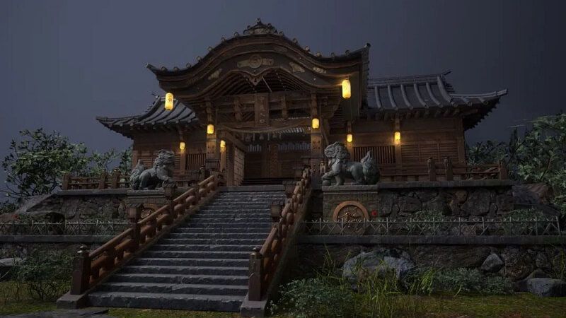
The leading cloud rendering service provider and render farm in the CG industry, Fox Renderfarm, will show you in this post a scene inside "For Honor," the Entrance, created by a student who is learning 3D modeling. The creator completed this work over a period of four weeks by solving problems and challenges with the help of his/her teacher and his/her own efforts. This article is a summary of his/her experience in the creation of this scene.Final result:Analyzing Concept Art &x26; Building Rough ModelsThis is a case of the PBR workflow, specifically utilizing 3ds Max for low-poly modeling, ZBrush for high-poly sculpting, TopoGun for retopology, Substance Painter and Photoshop for texture, and ultimately rendering with Marmoset Toolbag 4.To ensure production progress, in the early stages, the scene was initially constructed in 3ds Max based on the concept art as a large-scale reference for proportions, and then the actual production process began.Rough modelMaking Mid-poly ModelsHouse Structure: serving as the foundation of the scene framework. The house was divided into several parts for construction, including the roof, walls, floor, door frames, steps, and two side stone platforms. Through analyzing the concept art, it was determined that the stone walls and roof tiles employ a repeating texture pattern, which was subsequently applied throughout the scene.The scene props included stone lion statues, lanterns, ropes of hanging tassels, and more. Among them, the stone statues, steps, and several wooden elements were sculpted using ZBrush.The process of creating the mid-poly model involved continuously refining and adding more intricate details based on the rough model. It was important to analyze which models require sculpting and retopology during the initial stages of production, and which models could be reduced in detail to serve as the low-poly model. Conducting this analysis early on significantly improved efficiency in the production process.Mid-poly modelMaking High-poly ModelsThe high-poly modeling stage was relatively intense, involving numerous wooden doors, plaques, walls, as well as stone steps and statues. However, the task became less laborious when it came to identical wooden boards in the scene, as they could be easily adjusted and reused.Statue sculpting:Since the only element in this scene that required complete sculpting was the stone lion, I decided to challenge and improve my sculpting skills by starting from a sphere. After several days of sculpting, I began to see some progress. Then, with guidance from my teacher, I delved deeper into proportions, structure, and finer details.Props sculpting:The wooden boards, during the sculpting process, were meticulously sculpted stroke by stroke to enhance the texture and bring out the grain. Additionally, props like stone steps were also carved.Afterward, the UV unwrapping and baking process followed.Making Low-poly ModelsIn the early stages, we conducted an analysis of the assets. Among them, only the stone lion required retopology, while the remaining props could be obtained through reducing the mesh of mid-poly models.Overall, retopologizing the low-poly model is a relatively simple but patient task. There are several points to consider during the process: 1. Controlling the polygon count of the model. 2. Planning the mesh topology in a logical manner and determining whether certain details need to be retopologized. 3. Evaluating the density of the mesh topology for proper distribution.During the low-poly retopology stage, we encountered few difficulties. We followed a standard of 1m³/512 pixels to create the textures and planned them accordingly based on the predetermined pixel density. Then, we proceeded with UV unwrapping and layout. Throughout this process, we encountered issues such as seams appearing and models turning black. Eventually, we identified the problems as certain areas of the model lacking smooth group separation in the UVs and flipped normals. When placing the UVs, it is important to fully utilize the UV space to avoid wasting resources. Additionally, we needed to redo some of the UV work later on. It should be noted that in 3ds Max, when using automatic smoothing groups, it may not be apparent if the normals are flipped. Therefore, it is advisable to double-check after completing each section.Next was the normal map baking. We matched the high-poly and low-poly models in 3ds Max and ensured that there was some distance between all the models to avoid overlapping during the baking process. If any issues arose with the baked normals, we would repair them in Photoshop. Fortunately, there were no major problems throughout the entire baking process, so minor adjustments in Photoshop were sufficient.Low-poly modelMaking MaterialsI initially conducted material rendering for the sculpture and showed it to my teacher. However, the teacher pointed out some shortcomings. With guidance from the teacher, I gained a new understanding of material rendering. The key is to focus on volume first and then details. Volume here does not solely refer to the presence of volume under lighting conditions, but also the perception of volume even in the absence of lighting, relying only on colors. The addition of darker shades and textures further enhances the sense of volume in the model. Finally, sharpening was performed to make the details more prominent. By following this approach, the materials created would appear three-dimensional under lighting effects.RenderingAfter completing meticulous file organization, I standardized the naming of models, material spheres, and textures. This significantly reduced the workload when using Marmoset Toolbag 4. Once all the preparations were done, I began placing the models, setting up the lighting, adding special effects, and finally positioning the camera for rendering. During this process, a considerable amount of time was spent on lighting. The coordination between model materials and lighting never seemed to achieve the desired effect. However, with guidance from my teacher, I was able to improve the overall result.The above is our experience sharing the production process of the Entrance for the game "For Honor".Source: Thepoly
More
2023-09-28
The Ruins of David Made With 3ds Max & ZBrush
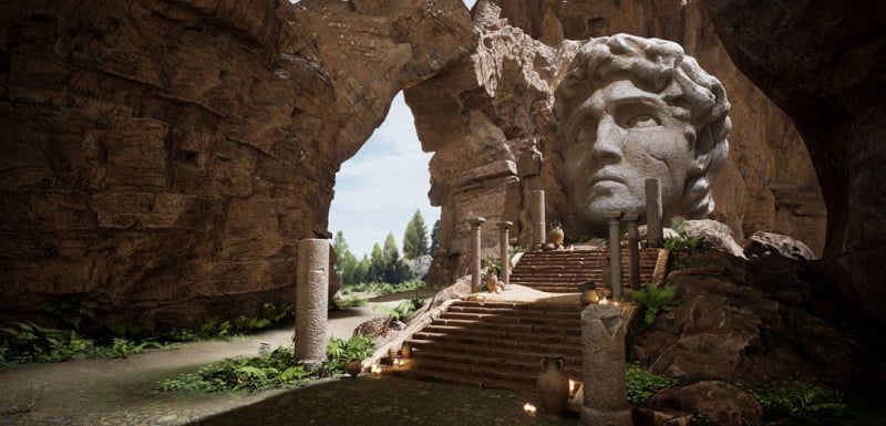
In this article, Fox Renderfarm, a leading cloud rendering service provider and render farm in the CG industry, will share with you a 3D scene called "The Ruins of David" that was collaboratively created by a student team over a span of 4 weeks with the PBR process.Final result:Observing and Analyzing Concept Art &x26; Asset AllocationOur reference was inspired by the work of a skilled artist we found online. It was our first attempt to collaboratively create a PBR scene from start to finish as a team. Throughout the process, we were constantly exploring and learning, but fortunately, we managed to complete the project in the end.For our scene, sculpting played a major role. We followed a production workflow that involved using 3ds Max for rough modeling, ZBrush for high-resolution sculpting, and then Topogun for creating low-polygon topology. During the high-resolution phase, we utilized KeyShot for rendering. Afterwards, we used Substance Painter, Photoshop, and Pixplant for texture and material creation. Finally, we rendered and outputted the scene using Unreal Engine 5.To ensure collaborative work while maintaining overall proportion unity, we initially need to establish the rough shape proportions and object placement based on the concept art. Afterward, we assigned tasks and divided the entire scene into five parts: the head of David, the distant mountains, the stairs and platform, the pillars and ornaments, and the background mountains with nearby rocks along with the obscured mountains in the foreground.Asset allocation chartLarge-scale scene constructionMaking Mid-poly ModelIn this scene, the only parts that required mid-poly modeling were the stone pillars, steps, and other small objects. For the rest of the scene, we mainly used a box or sphere shape and directly imported them into ZBrush for sculpting.Mid-poly model of small objectsMaking High-poly ModelCompared to the leisurely mid-poly modeling stage, the high-poly modeling phase is much more lengthy and complex. Approximately 90% of the entire scene required using ZBrush for high-resolution sculpting. Since most objects during the mid-poly modeling stage were very rough, we not only had to shape them but also focus on capturing intricate details. We conducted extensive research and decided to focus on creating a desert and wind-eroded terrain. The majority of the artificial objects in the scene were made of sandstone. During the sculpting process, we had to ensure the integrity of the main structure while considering the effects of wind erosion on the material surface, such as which structures would be eroded and which ones would be preserved. We went through many trial-and-error stages. Initially, we struggled with rigidly replicating the structures, but with guidance from our instructor, we eventually found the correct approach. By closely observing real mountains and wind-eroded statues, we finally achieved the desired aesthetic.Sculpting of Mountain StonesSculpting of pillars and small objectsSculpting on the side of the stoneWhen creating the sculpture of David, as it was our first time sculpting a human figure, we had to make countless modifications just to get the lips right. One moment, it would resemble a rugged, masculine face, and the next moment, it would transform into a delicate, feminine one. It must be said that facial sculpting for the character was indeed one of the challenges in this scene. Even the slightest change could disrupt the overall proportions. There were moments when I looked at the ugly face I sculpted and felt like giving up. Fortunately, with guidance from our instructor and numerous revisions, we were able to somewhat capture the essence of Michelangelo's David.Sculpting of the Statue of DavidFailed versionOf course, there were many other challenges besides these. The making of the candles was also a headache. We struggled for a long time to recreate the true essence, so we decided to simply buy two large candles. We burned them day and night until they finally took on the appearance we desired.Candles dedicated to the artsSculpting of candlesMaking Low-poly ModelIf the previous process was more like creation, then making the low-poly models is more like streamlining and finalizing the previous work. We used two methods to create low-poly models. One method involved using ZBrush's automatic retopology tools to generate the low-poly models, and then organizing the topology in 3ds Max through subtraction. The second method, used for objects like heads and candles, involved using Topogun for retopology. This method required patience and attention to detail. We needed to ensure simplicity, comply with proper topology standards, and also preserve the silhouette contours and main structures as much as possible.Low-poly of Statue of DavidAfter the topology phase, we moved on to the stage of UV unwrapping and baking normal maps. UV unwrapping may seem like an ordinary process, but it actually has a significant impact on the final result. If not done properly, it may even require rework in the later stages. To ensure consistent UV size, we adopted a pixel density of 256 pixels per cubic meter (256/m³) for our production.After the UV layout was completed, the next step was baking. We needed to match the high-poly and low-poly models as closely as possible in 3ds Max, ensuring minimal gaps or low matching accuracy. Afterwards, we exported the models to Substance Painter for baking the normal maps and ambient occlusion (AO). However, due to our limited experience, we often encountered rainbow artifacts, which required numerous iterations of rework. In some cases where certain issues were difficult to resolve, we directly hand-painted the normals using Photoshop to solve the problem.For different materials, we adopted a method of using material balls to differentiate them. It is crucial to have standardized naming conventions for the material balls, as any lack of consistency in naming can lead to significant difficulties during the later stages of production.Making MaterialsWe put a lot of effort into sculpting the details, while the material aspect was relatively easier. We adopted the standard PBR (Physically Based Rendering) workflow for material creation. We focused on establishing the overall volume first and then added specific details such as weathering and cracks. Unlike individual material creation, the team's material production required coordination among members to achieve a unified artistic style and texture. Objects with the same material were assigned identical generators and material balls to maintain consistency in the art style, while incorporating different details to avoid excessive repetition.To avoid significant discrepancies between different team members' work, we would apply similar materials to the engine and observe the overall effect. This allowed us to determine how to modify the materials to ensure a consistent and cohesive final result.RenderingFrom the beginning of the production, we planned to do the final rendering in UE5 (Unreal Engine 5). In order to achieve this goal, we worked overtime and studied UE5 for more than a week. During this stage, we faced considerable difficulties and had to explore and learn as we progressed. We were challenged by various nodes and encountered obstacles along the way. Thankfully, we managed to resolve most of the issues in the end.Making of terrain material ballsCandle making was also a challenging aspect. In order to achieve the effect of flickering flames and dynamic firelight, we chose to use the Niagara particle system for the candle. We worked overtime for several days specifically to study and develop this relatively fundamental effect for the candle's flame.Fire particle effectsRenderingConclusionThe above is our experience and insights into the entire production process. Together, we faced many unprecedented challenges and encountered new software and knowledge. However, with the collective efforts of all team members, we successfully overcome those obstacles. We would like to express our gratitude and appreciation to everyone for their hard work and dedication!Fox Renderfarm is a 3ds Max cloud rendering service provider and 3ds Max render farm dedicated to bringing more useful tutorials to our 3ds Max users. We are offering a free $25 render trial to all new users, get rendering to free up your computer now.Source: Thepoly
More
2023-08-10
Get Started on Game Modeling with 3ds Max Modeling Tips
The reason why 3D is called "3D" is because it takes a 2D profile of an object and extrudes it along a certain path, forming complex 3D objects. Different shapes can be applied to different segments along the same path. This transformation path is called loft modeling. Today, Fox Renderfarm, as a leading cloud rendering service provider and render farm in the industry, will introduce the basic modeling techniques 3ds Max loft modeling to you.Lattice ModelingMaya's powerful lattice modeling tool is incredibly powerful but often overlooked by beginners. The lattice allows you to efficiently make overall changes to high-resolution models, avoiding the tedious task of manipulating hundreds or thousands of edges and vertices individually.Despite being a powerful tool, lattice modeling is often missed by beginners, partly because it is located under the Animation tab rather than the Polygon Modeling tab in Maya's interface.Image from Internet, copyright of the original authorSoft SelectionAre you tired of moving each vertex individually?Just like the lattice modeling, the soft selection feature allows you to efficiently modify a region of a model by setting a controllable falloff radius for each vertex, edge, or face. In other words, when soft selection is enabled, selecting a vertex and translating it in space will also affect the surrounding vertices (the degree of influence is determined by the falloff radius you have set).Soft selection is particularly useful for modeling organic objects such as skeletons, muscles, and faces. It helps you achieve smoother transitions and deformations between different parts of the model.Image from Internet, copyright of the original authorThe Duplicate SpecialHave you ever been frustrated while modeling objects with regularly spaced elements, like fences? The Duplicate Special feature allows you to create multiple copies of an object and translate, rotate, or scale each instance individually.For example, let's say you need to model a Greek pillar with a series of regularly spaced relief units encircling its surface. In this case, after creating a single relief unit, you can find the central axis of the cylinder and use the duplicate special feature to evenly distribute and replicate each relief unit, making it easy to complete the modeling process.Image from Internet, copyright of the original authorThe Relax BrushBeginners often tend to end the modeling of organic models with a "blocky" appearance. Although Maya does not have a complete set of sculpting tools, it does have some basic sculpting brushes, with the most useful one being the Relax Brush tool.The Relax brush will average out the spacing between the vertices you brush over, resulting in a smoother surface without compromising the model's overall shape. If you are modeling a facial model, for example, you can use the Relax brush to make the blocky face appear more like a smooth skin surface.Find mesh tool under the polygons menu, then sculpt geometry tool, click on the little square behind this option, and find sculpt parameter under properties, locate relax brush, and then go back to the 3D view and brush the vertices you want to smooth.Alternatively, you can select the object you are currently modeling, hold down the right mouse button until a menu appears, and then choose Paint -> Sculpt. In the Sculpt Parameters, select the Relax Brush. You can also modify the brush radius and strength in the brush options tab to control the brush effect.Image from Internet, copyright of the original authorSelection SetsHave you ever had this experience: After spending a long time carefully selecting complex faces, edges, and vertices, and performing a series of operations, you unselect them to start working on something else. Then you realize that you need to make further adjustments to the large area you originally selected, but you have already canceled your previous selection. Now you have to go through the frustration of manually clicking and selecting points, edges, and faces again.Actually, this can be avoided. Maya allows you to save selection sets so that you can quickly and easily activate them later on.If you find yourself repeatedly selecting the same points, edges, or faces, or if you have just spent a lot of time selecting a large area and suspect that you may need to select that area again in the future, use the Command Selection Sets to save it.Select the desired points, edges, or faces, then go to Create -> Quick Select Sets. Name the set and click "OK." (If you want to find it on the toolbar later, click "Add to Shelf"). To quickly select this area in the future, simply go to Edit -> Quick Select Sets and locate your named selection set in the list.Interact with Others MoreMany beginners often overlook this step and rely solely on hard work. While professionals in the workplace can easily communicate with colleagues in the industry, it can be more challenging for beginners.Beginners can exchange experiences with classmates who are learning together, or engage with unfamiliar peers on social platforms and other forums.Regardless of the approach, it is always beneficial to look at other people's work. Hopefully, with the guidance of these tips, everyone can achieve great success.If you have problems with slow 3ds Max rendering on your own computer, you can use a 3ds Max render farm that offer fast cloud rendering service to speed up your 3ds Max rendering and meet your project's delivery date.Source: aliyun
More
2023-07-27
Business Consulting

Global Agent Contact: Evan Zhang

Email: evan.zhang@foxrenderfarm.com

Marketing Contact: Evan Liu

Email: evanliu@foxrenderfarm.com

Message Us:
Newsletter
Keep up with our latest software updates, special offers and events!
Copyright © 2025 FoxRenderfarm.com. All Rights Reserved.