Up To 40% Bonus On Your First Rechargeclose

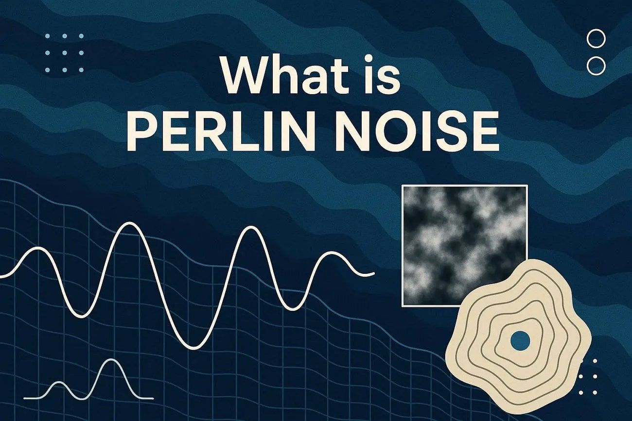
What Is Perlin Noise? Definition, Principles, and Workflow

Imagine a digital world where clouds drift, rivers flow, and mountains rise without looking artificial. Perlin noise makes this possible by creating smooth, natural patterns that do not repeat.

Understanding perlin noise definition, principles, and workflow enables you to shape digital landscapes and effects in ways that feel natural. This guide explains what Perlin Noise is, how it works, its key concepts, and a stepwise workflow. 

perlin noise guide


Part 1. What Is Perlin Noise?

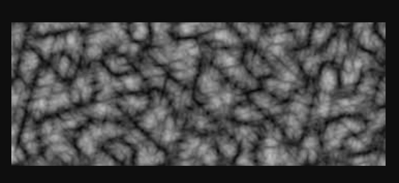
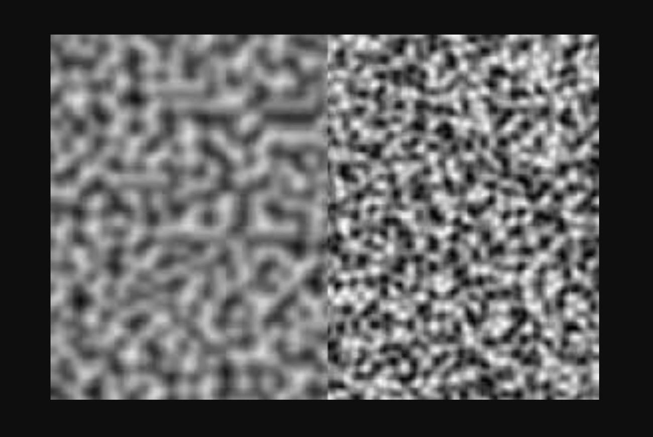
Perlin noise is a type of gradient noise created by Ken Perlin in 1983. It was first used in the film Tron to make computer graphics look more natural and less perfect or plastic. Unlike conventional random noise, which resembles TV static, Perlin noise produces smooth, continuous patterns. This makes it ideal for creating natural effects in computer graphics.

perlin noise definition

Main Features

This gradient noise has special features that make it helpful for artists and developers.

  1. Coherent Randomness: Values near each other are related, so patterns appear smooth instead of scattered or noisy.
  2. Gradient-Based Construction: A grid of random gradient directions interacts with positions; then, smooth blending creates natural patterns.
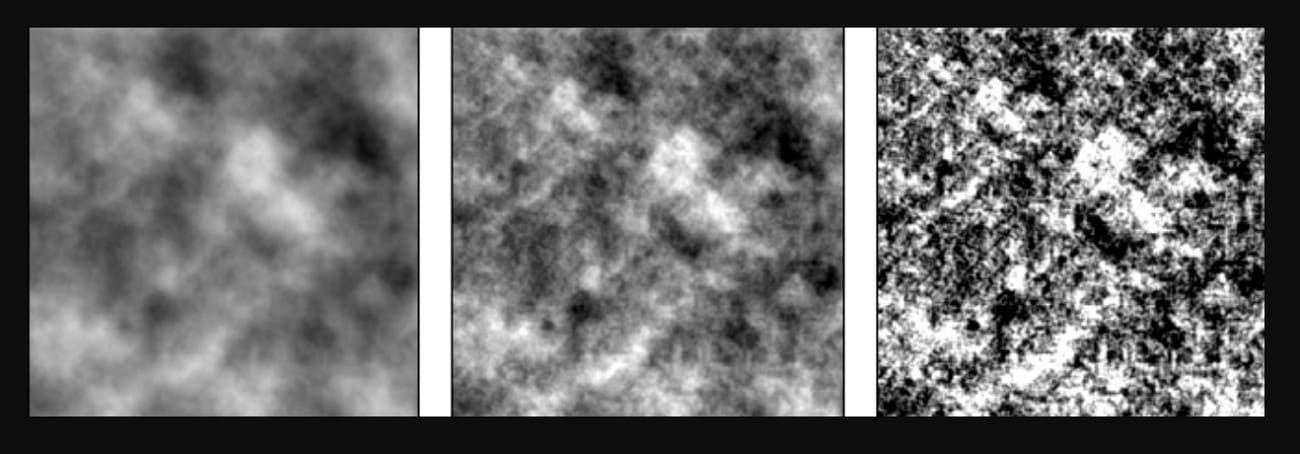
  3. Multi-Octave Structure: Multiple layers of Perlin noise combine at different sizes and strengths, controlling big shapes and small details.
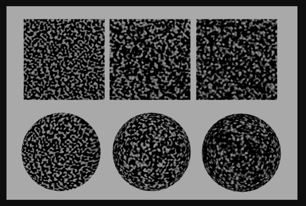
  4. Dimensional Flexibility: Works in 1D, 2D, 3D, or more, so it can create textures, volumes, or changing effects over time.
  5. Repeatability: Using the same input and seed always gives the same output, which is useful for consistent procedural results.

Common Categories and Variants

Perlin Noise, or Noise Perlin, usually refers to the basic algorithm, but it often comes in different types or versions.

By Dimension

  • 1D Noise: Used for simple changes over time, such as animation curves or time-based effects.
  • 2D Noise: Commonly used for textures, height maps, and patterns that appear on flat surfaces.
  • 3D/4D Noise: Applied to the volumetric impacts like clouds or smoke, and effects that change across space and time.

perlin noise dimension

By Octave/Composition Style

  • Basic Perlin Noise: Single layer of noise, smooth and straightforward in structure.
  • Fractal Brownian Motion: Combines multiple layers of Perlin Noise with different sizes and strengths to add detail.
  • Billow Noise: Uses the absolute value of noise to create soft, rounded shapes like clouds or gentle hills.
  • Ridged Noise: Converts noise into sharp ridges, ideal for mountains and rough surfaces.

perlin noise style


Part 2. History and Evolution of Perlin Noise in 3D Graphics and Animation

The history of Perlin noise shows how a need led to an invention. It helped computer graphics change from rigid, plastic shapes to more natural, real-world looks.

Origins

  • Inventor: Ken Perlin, an American computer graphics researcher and professor.
  • Time: Early 1980s.

In 1983, Ken Perlin worked on the movie Tron, where the effects required realistic textures such as marble, wood, clouds, and fire, and normal random noise made harsh, unnatural patterns. Hence, Perlin created a noise function that gave smooth, natural results.

perlin noise pioneer

Early Development

1982–1983 (Developed then, published 1985): Perlin introduced the original Perlin Noise algorithm.

Concept: Instead of using random values at each point, he used pseudo-random gradient vectors on a grid and interpolated values smoothly between points.

First Major Use

  • In the Film Industry, Tron (1982) had some early experimentation with noise-based textures.
  • Star Wars: Episode I - The Phantom Menace (1999) and later movies widely used Perlin Noise for CGI textures and particle effects.

This invention enabled artists and programmers to create realistic, natural textures automatically, so they did not need hand-drawn textures.

perlin noise evolution

Improvements and Variations

After the original 1985 version, Perlin noise evolved, and the given points explained how: 

  • Improved Perlin Noise (2002): Ken Perlin released an improved version to remove visual errors and reduce directional bias. It uses simpler gradient selection and better interpolation.
  • Simplex Noise (2001–2002): It was also developed by Ken Perlin, and Simplex Noise works faster and cleaner in higher dimensions. It reduces computation load and minimizes visual artifacts while keeping realistic gradient-based patterns intact.
  • Extensions: Multi-octave or fractal noise uses several Perlin noise layers at different sizes to add texture detail. Today, it helps create game terrains, clouds, smoke, fire, and even sound effects.


Part 3. How Perlin Noise works

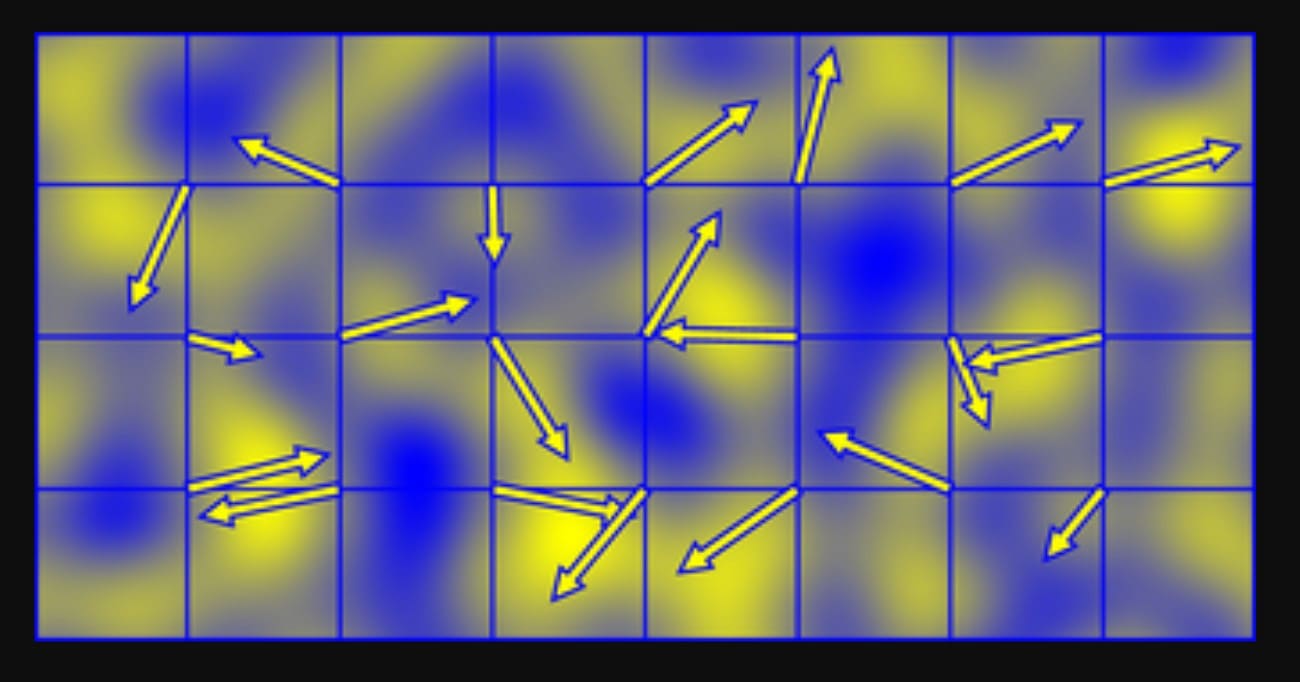
The Perlin noise algorithm works by dividing space into a regular grid in 1D, 2D, or 3D. Each corner of the grid does not store a random number; rather, it stores a pseudo-random direction vector, called a gradient.

When you ask for a noise value at any point, the algorithm looks at the nearby grid corners. It checks how far the point is from each corner, measures how well the corner’s gradient points toward that location, and then smoothly blends all corner influences into one final value.

perlin noise working

Step-by-step process (2D Example)

1. Find The Grid Cell: 

For a point (x, y), the algorithm first finds which grid cell contains it, and this is done by taking the floor of the coordinates:

The bottom-left corner of the cell becomes (i, j) = (⌊x⌋, ⌊y⌋).

Next, it calculates the position of the point inside the cell:

  • xf = x − i
  • yf = y − j

Both values stay between 0 and 1.

2. Get Gradients at The Cell Corners: 

Each of the four corners of the cell has a unit gradient vector:

  • (i, j)
  • (i + 1, j)
  • (i, j + 1)
  • (i + 1, j + 1)

These gradients are chosen using a permutation table. This makes them appear random but remains consistent when the same grid point is used.

3. Measure Corner Influence with Dot Products: 

For each corner, the algorithm builds a vector from that corner to the point.

For example, from (i, j) to (x, y), the vector is (xf, yf).

  • It then takes the dot product between this offset vector and the corner’s gradient vector.
  • If the gradient points toward the point, the value is positive.
  • If it points away, the value is negative.
  • If it is sideways, the value is near zero.

This tells how strongly each corner affects the final noise value.

4. Smooth Values Using the Fade Function:

Before blending the corner values, a smooth fade curve is applied to xf and yf:

f(t) = 6t⁵ − 15t⁴ + 10t³

This curve flattens at the edges of each cell, which prevents visible seams and keeps the noise smooth across grid boundaries. 

5. Interpolate The Corner Results: 

First, the algorithm blends the bottom left and bottom right corner values using the faded xf value. It does the same for the two top corners, then blends those two results vertically using the faded yf value. The final result is the Perlin noise value at (x, y), usually between −1 and 1.


Part 4. Perlin Noise Workflow - Game Terrains Example

Perlin noise creates terrain by sampling a smooth noise field over a grid, and each noise value becomes a “height.” Multiple layers add detail, producing mountains, hills, and plains, and the heightmap can control meshes, textures, and biomes in games.

perlin noise example workflow

Basic Heightmap Workflow

1. Sample noise over a 2D grid: 

  • For each grid cell or vertex (x, y), compute:
    n = noise(x * frequency, y * frequency)
  • Low frequency (0.01–0.05) gives broad hills. High frequency gives small bumps.

2. Map noise to height: 

  • Normalize noise from [-1, 1] to [0, 1].
  • Scale to terrain range:
    height = minHeight + n * (maxHeight - minHeight)
  • Store heights in a heightmap array.

3. Build the terrain mesh: 

  • In Unity, Unreal Engine, or other engines, assign height values to terrain or mesh vertices.
  • The engine creates smooth hills and valleys.

Multi-Octave / Fractal Terrain

Single-layer noise looks flat. Multiple octaves give detail.

Steps:

For each octave, sample noise at a higher frequency and lower amplitude:

  • value += noise(x * freq, y * freq) * amplitude

Multiply frequency by lacunarity (≈2.0) and amplitude by persistence (≈0.4–0.6).

Result:

  • Low-frequency octaves create large landforms.
  • High-frequency octaves add small bumps and realistic detail.

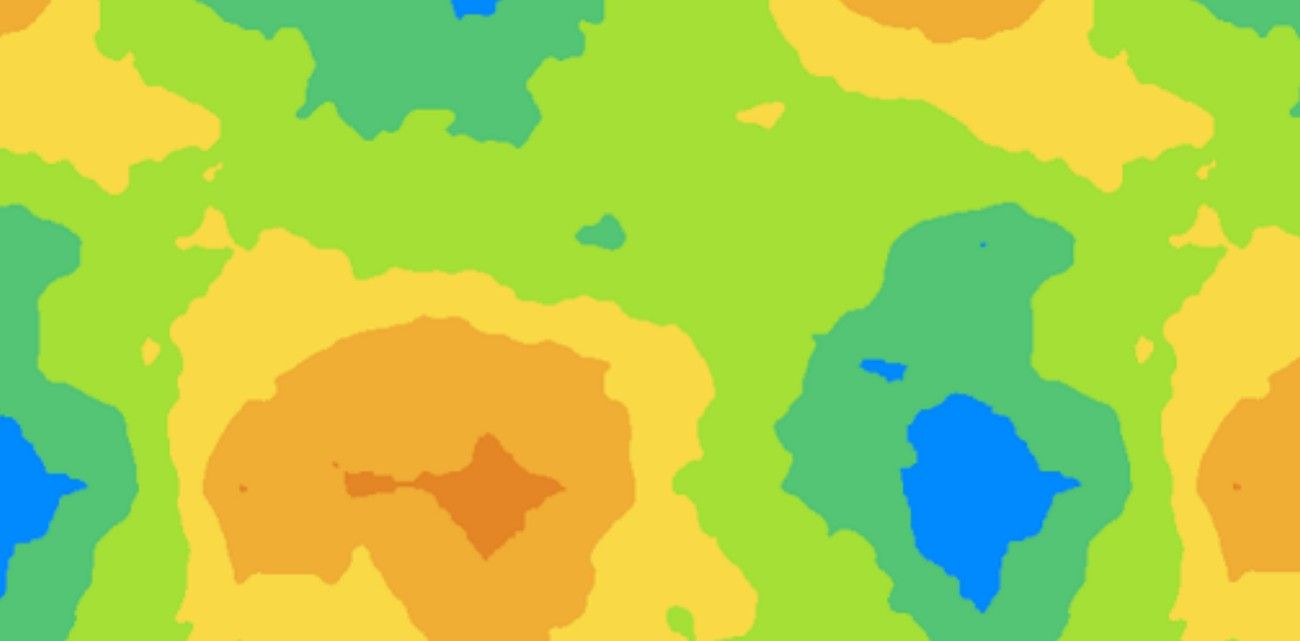
Terrain Types from Height

Assign terrain types based on height:

  • < 0.3 → water
  • 0.3–0.4 → beach
  • 0.4–0.7 → grassland
  • > 0.7 → rock/snow

Assign colors or textures in the same way (e.g., blue, green, grey, white).

Common Game Patterns

  • Static Worlds: Generate a full heightmap at startup and assign it to terrain or mesh.
  • Infinite/Chunked Worlds: Use world coordinates plus a seed. Chunks are created on the fly but remain consistent.
  • Biomes and Features: Combine multiple noise maps (height, temperature, moisture) to place forests, deserts, lakes, and other terrain features.


Part 5. Perlin Noise vs Simplex Noise

Both simplex vs Perlin noise were made by Ken Perlin to fix the artificial look of computer graphics. Simplex noise was created to improve Perlin noise by working faster in higher dimensions and removing grid-like patterns.

perlin noise and simplex noise

Conceptual Comparison: Square vs. Triangle

Ideally, Perlin and Simplex noise use coherent gradient noise. They place random gradients on a grid, calculate dot products with offsets, and blend values smoothly.

Lattice Structure

  • Perlin Noise: Uses a regular grid like squares in 2D, cubes in 3D, hypercubes in higher dimensions, and each point blends the nearest 2ⁿ corners.
  • Simplex Noise: Uses simplices like triangles in 2D, tetrahedra in 3D, and each point blends only n+1 corners.
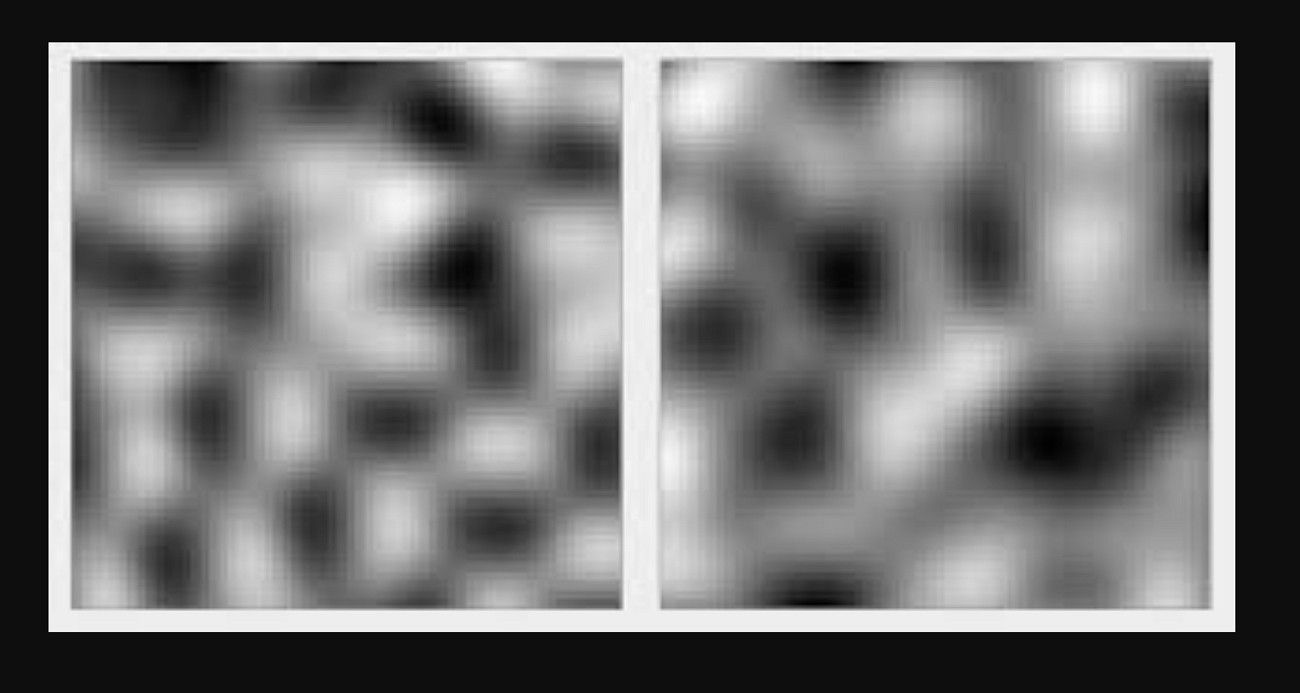
perlin noise composition

Visual Look

  • Perlin Noise: Can show grid-aligned or directional patterns, especially at low resolution or high frequency.
  • Simplex Noise: Looks more uniform in all directions, with hexagonal features and fewer visible patterns.

Performance Comparison

Feature

Perlin Noise

Simplex Noise

Complexity

Uses all 2^n corners of the nD hypercube.

Uses only  n+1 simplex corners in nD.

2D Performance

Very fast (built into many engines).

Slightly faster or comparable.

4D+ Performance

Very slow; heavy memory/CPU load.

High performance; ideal for time-based 4D.

Hardware Use

More complex to implement in GPUs.

Designed for easy hardware implementation.

Best-suited Scenarios

Learning simple 2D/3D patterns, when artifacts are acceptable.

High‑dimensional noise, artifact‑sensitive visuals, volumetrics, and real‑time with many samples.

Summary: When to Choose Which?

Use classic Perlin noise when you primarily work in 1D, 2D, or 3D and do not require extreme performance. It provides a simple, well-documented algorithm with many examples in games, shaders, or quick prototypes.

However, use Simplex noise when you need 3D, 4D, or higher noise for volumetric effects or animated fields, and speed matters. It also produces smoother, more uniform patterns with fewer directional artifacts.


Part 6: Applications of Perlin Noise

Perlin noise is more than an art tool and is a key algorithm used in many fields to create smooth, natural-looking patterns that mimic real-world randomness.

1. Film and Animation

Perlin noise is used to generate realistic textures on various objects such as clouds, smoke, fire, water, and other natural effects in films and animation works. Perlin noise enables artists to make complex surfaces without detailing each detail by hand, and saves time and increases visual realism.

Examples are Star Wars visual effects, Tron textures, and fluid simulations in films such as Finding Nemo by Pixar.

perlin noise in film and animation

2. Video Games

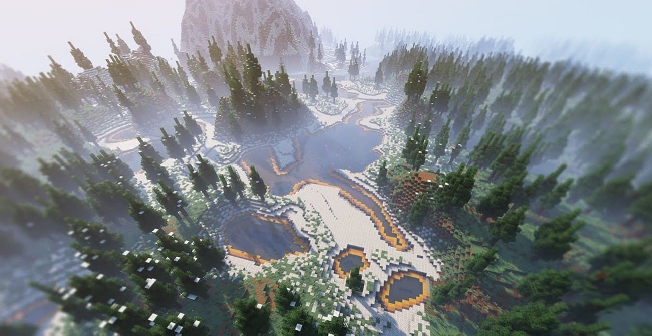
Game developers use Perlin Noise to generate terrain, landscapes, caves, and procedural worlds. It is also used to generate material textures, simulate surfaces of water, and introduce natural variability to objects and environments.

As examples, the terrain generator of Minecraft, the planetary surfaces of No Man's Sky, and the natural textures of Fortnite or The Witcher series.

perlin noisein video games

3. Architecture and Design

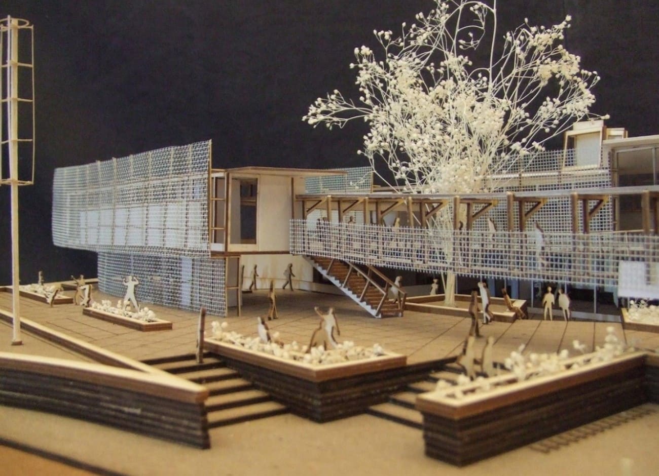
Architects and designers have applied the Perlin noise to generate realistic procedural textures on building materials, including wood, marble, and stone. It is also useful in the modeling of landscapes and the visualization of natural environments.

Examples are procedural wood and marble surfaces in architectural renderings, realistic garden or park models, and interior design models.

perlin noise in design

4. Simulation and Scientific Visualization

In simulations of clouds, fluids, fire, and other natural phenomena, Perlin noise generates realistic patterns. It is also used in medical imaging, meteorology, and environmental simulations to add natural variation.

For example, weather simulations, fluid dynamics studies, and visualizations of ocean waves or smoke in research and training software.

perlin noise in scientific visualization

5. Art and Creative Coding

Digital artists use Perlin Noise to create generative art, procedural patterns, and dynamic visual effects. It enables controlled randomness to produce visually appealing results.

Examples include Processing sketches for flowing patterns, digital wallpapers, procedural textures in Adobe After Effects, and interactive web art using p5.js.

perlin noise in coding and art


Part 7. How Perlin Noise Impacts Rendering Performance

In real production workflow, when perlin noise is used extensively in procedural textures, volumetric effects, and displacement-driven surfaces, its impact on rendering performance becomes significant.

In practical projects, Perlin noise is rarely applied as a single layer. Artists often combine multiple octaves to increase detail, drive displacement maps for terrain, or control volumetric density for clouds, smoke, and fog. Each added layer increases shader complexity, sampling frequency, and memory usage during rendering.

For volumetric effects, Perlin noise is frequently evaluated many times along each ray through the volume. This ray-marching process dramatically raises render time, particularly in high-resolution frames or animation sequences where consistency across frames is critical.

This brings several common challenges like longer render times per frame, GPU memory pressure, and reduced efficiency. To handle these of Perlin-noise-based scenes, many studios and independent creators turn to cloud rendering solutions.

Fox Renderfarm provides large-scale GPU and CPU cloud rendering resources designed for complex 3D scenes and procedural workflows. By distributing frames and tasks across high-performance render nodes, this render farm allows artists to process heavy volumetric effects, procedural terrains, and noise-driven materials without being constrained by local hardware limitations.

For projects that rely heavily on Perlin noise, such as cinematic visual effects, large environments, or animation sequences, cloud rendering helps shorten render times while preserving visual quality.

task-overview.png


Conclusion

To sum up, Perlin noise is a powerful technique that adds natural, smooth patterns to digital creations. Since this guide has compared it with Simplex noise, understanding both algorithms helps creators choose the right method.

Additionally, for accurate and efficient rendering, using a trusted cloud rendering service like Fox Renderfarm is highly recommended.

Interested

How to Create the Entrance of 'For Honor'
The leading cloud rendering service provider and render farm in the CG industry, Fox Renderfarm, will show you in this post a scene inside "For Honor," the Entrance, created by a student who is learning 3D modeling. The creator completed this work over a period of four weeks by solving problems and challenges with the help of his/her teacher and his/her own efforts. This article is a summary of his/her experience in the creation of this scene.Final result:Analyzing Concept Art &x26; Building Rough ModelsThis is a case of the PBR workflow, specifically utilizing 3ds Max for low-poly modeling, ZBrush for high-poly sculpting, TopoGun for retopology, Substance Painter and Photoshop for texture, and ultimately rendering with Marmoset Toolbag 4.To ensure production progress, in the early stages, the scene was initially constructed in 3ds Max based on the concept art as a large-scale reference for proportions, and then the actual production process began.Rough modelMaking Mid-poly ModelsHouse Structure: serving as the foundation of the scene framework. The house was divided into several parts for construction, including the roof, walls, floor, door frames, steps, and two side stone platforms. Through analyzing the concept art, it was determined that the stone walls and roof tiles employ a repeating texture pattern, which was subsequently applied throughout the scene.The scene props included stone lion statues, lanterns, ropes of hanging tassels, and more. Among them, the stone statues, steps, and several wooden elements were sculpted using ZBrush.The process of creating the mid-poly model involved continuously refining and adding more intricate details based on the rough model. It was important to analyze which models require sculpting and retopology during the initial stages of production, and which models could be reduced in detail to serve as the low-poly model. Conducting this analysis early on significantly improved efficiency in the production process.Mid-poly modelMaking High-poly ModelsThe high-poly modeling stage was relatively intense, involving numerous wooden doors, plaques, walls, as well as stone steps and statues. However, the task became less laborious when it came to identical wooden boards in the scene, as they could be easily adjusted and reused.Statue sculpting:Since the only element in this scene that required complete sculpting was the stone lion, I decided to challenge and improve my sculpting skills by starting from a sphere. After several days of sculpting, I began to see some progress. Then, with guidance from my teacher, I delved deeper into proportions, structure, and finer details.Props sculpting:The wooden boards, during the sculpting process, were meticulously sculpted stroke by stroke to enhance the texture and bring out the grain. Additionally, props like stone steps were also carved.Afterward, the UV unwrapping and baking process followed.Making Low-poly ModelsIn the early stages, we conducted an analysis of the assets. Among them, only the stone lion required retopology, while the remaining props could be obtained through reducing the mesh of mid-poly models.Overall, retopologizing the low-poly model is a relatively simple but patient task. There are several points to consider during the process: 1. Controlling the polygon count of the model. 2. Planning the mesh topology in a logical manner and determining whether certain details need to be retopologized. 3. Evaluating the density of the mesh topology for proper distribution.During the low-poly retopology stage, we encountered few difficulties. We followed a standard of 1m³/512 pixels to create the textures and planned them accordingly based on the predetermined pixel density. Then, we proceeded with UV unwrapping and layout. Throughout this process, we encountered issues such as seams appearing and models turning black. Eventually, we identified the problems as certain areas of the model lacking smooth group separation in the UVs and flipped normals. When placing the UVs, it is important to fully utilize the UV space to avoid wasting resources. Additionally, we needed to redo some of the UV work later on. It should be noted that in 3ds Max, when using automatic smoothing groups, it may not be apparent if the normals are flipped. Therefore, it is advisable to double-check after completing each section.Next was the normal map baking. We matched the high-poly and low-poly models in 3ds Max and ensured that there was some distance between all the models to avoid overlapping during the baking process. If any issues arose with the baked normals, we would repair them in Photoshop. Fortunately, there were no major problems throughout the entire baking process, so minor adjustments in Photoshop were sufficient.Low-poly modelMaking MaterialsI initially conducted material rendering for the sculpture and showed it to my teacher. However, the teacher pointed out some shortcomings. With guidance from the teacher, I gained a new understanding of material rendering. The key is to focus on volume first and then details. Volume here does not solely refer to the presence of volume under lighting conditions, but also the perception of volume even in the absence of lighting, relying only on colors. The addition of darker shades and textures further enhances the sense of volume in the model. Finally, sharpening was performed to make the details more prominent. By following this approach, the materials created would appear three-dimensional under lighting effects.RenderingAfter completing meticulous file organization, I standardized the naming of models, material spheres, and textures. This significantly reduced the workload when using Marmoset Toolbag 4. Once all the preparations were done, I began placing the models, setting up the lighting, adding special effects, and finally positioning the camera for rendering. During this process, a considerable amount of time was spent on lighting. The coordination between model materials and lighting never seemed to achieve the desired effect. However, with guidance from my teacher, I was able to improve the overall result.The above is our experience sharing the production process of the Entrance for the game "For Honor".Source: Thepoly
More
2023-09-28
Learn How to Make a Handheld Fan in 3D
Today, Fox Renderfarm, the industry's leading cloud rendering service provider and render farm, will bring you a 3D tutorial that explains how to make a handheld fan. Let's get started right now.First import the image, use the straight line tool to draw the length of the handle, then use the rotational molding tool to create the handle and add a cover.Generate a rectangle using the center point, adjust it to the appropriate size, and then generate a circular runway. At this point, use the fitting tool to get the appropriate shape.Select the circular runway that was just generated, hold down Shift to extrude the faces on both sides and add a cover, then use the shell tool to shell both sides.Copy the inner edge line of the shell, extrude the face and add the cover, pull off the inner face to keep only the outer side, and then chamfer to generate the outer layer of the shell that needs to be hollowed out.Use curves to draw the edge shape of the connecting axis, then use rotational molding to generate the surface, and then add the cover to generate the solid.Connect the rectangle diagonal, use the diagonal to generate a round tube, and adjust the angle and thickness of the tube so that the angle and thickness of the tube match the reference picture.Draw a diagonal line again and use the Line Array tool to array along this line, where the number of arrays is 18.Use the object intersection line function to select the round tube and the shell to be hollowed out, determine whether the position matches by the object intersection line, adjust the position and then cut to get the hollowed out object.Use the Rectangle tool to generate a runway circle, adjust it to the right size, then cut and combine it with the hollow object and offset it inward to get the solid. The same can be done for the outer runway circle, here you need to make a copy of the hollow object for backup.Use the mirror tool to mirror the hollowed-out model made in the previous step to the back, then use the method in the fourth step to get an unhollowed-out shell, generate a rounded rectangle and cut it according to the second reference picture, then use the combination tool to combine, and finally offset the surface to get the solid.Use a rectangle to frame the size of the button, then use a straight line to connect the midpoint of the rectangle, next use the center point tool to generate a circle, and squeeze the circle to the right size and adjust the height of the button.Split the button and the handle for spare, and then chamfer the top of the handle for the next step.For the base, again using the rotational molding tool. First draw the edge shape using curves, then rotate the shape and cap it to create a solid.Now perform the Boolean split between the handle and the base, then detach the surface. Next, copy the edge line, move the inner circle downwards, use the double rail sweep to generate the surface and combine it to obtain the base shape.Use the center point circle and rectangle tools to generate the button and indicator light shapes on the handle, extrude the solid and then perform a boolean split with the handle to get the handle shape and the indicator light.Use the Rectangle to create the runway circle and rotate it 45° to get the "x" below, then use the Trim tool to trim off the excess lines and combine them. After extruding the surface, use the Boolean split tool to split it to get the "x" icon.Now create the circular texture on the button. First abstract the structure line to get a button-sized circle, then generate a circle solid at the circle node, and use the Array Along Curve tool to make an array. Arrange the five columns in sequence according to the image and mirror them to get the desired texture. Finally, we use Boolean split to get the button shape.Chamfer the intersection of the button and the handle, and chamfer the intersection of the handle and the base.Use the curve to draw the fan shape, then use the XN tool to generate the surface, and array along the center point. The number of arrays here is 5. Adjust the fan blade position and extrude the fan blade solid.Check the model and chamfer it to complete the model.The next step is to render the product. First, divide the product into four layers, one for the orange object, one for the flesh-colored object, one for the metal connection, and one for the self-illumination. Then start rendering.First adjust the model position by aligning the model to the ground in the Advanced Options.Set the model materials to the model in turn. Note that you need to turn down the metallic shine of the metal joints in order to get a frosted look.Adjust the self-luminous material on the handle to the right intensity in accordance with the light, and choose white as the color.Set the setting options in the image to Press Exposure, High Contrast, and Photography.Change the background color in the environment settings. Use the straw tool to absorb the image color, turn down the brightness of one light in the HDR editor, hit the light on the hollow surface, adjust the shape of the light to rectangle, and then hit a main light on the left side of the product to make a shadow appear on the right side.Adjust the object position in the camera, lock the camera, and finish the rendering.Source: YBW
More
2023-07-20
How to Use VFace and Make Effects in Arnold?
In this article, Fox Renderfarm, the CG industry's leading cloud rendering service provider and render farm, will share with you how to use VFace and how to restore effects in the Arnold renderer. The author is CaoJiajun.Firstly I purchased some VFace materials from the official website to get the following files.We will mainly use the above files for this sharing, they are our main materials to make high quality details of the face. VFace provides 2 types of facial models, one for the head with open eyes and one for the head with closed eyes, choose one of them according to your needs. If you are doing a model that needs to be animated with expressions in post, I would recommend choosing the model with closed eyes, as the open eyes model will cause the eyelids to stretch when you do the blink animation. You don't need to worry about this for still-frame work.Let's start with the production process. It's actually very simple, wrap your own model with a VFace model through Wrap or Zwrap, then pass the map and finally render it in Maya or other 3D software. The process is simple but there will be a lot of things that need to be taken care of in there otherwise the facial details will not be rendered correctly.1 Model CleaningFirst we need to load the model provided by VFace into ZBrush and match it to our sculpted model.Then you can head into Zwrap or Wrap for wrapping.Lastly, the wrapped model is imported into ZBrush to replace the VFace model.In ZBrush we use the Project brush to match the face of the wrapped model more precisely to our own sculpted model, once matched you will have a model that matches your sculpted model perfectly, at this point we can go into Mari for the map transfer.2 Using Mari to Transfer the MapIn Mari we first set up the project, import our own sculpted model or the wrapped and matched XYZ model, then remove the other channels in the Channels and keep only the Basecolor channel, and we can customize the channels as we wish.What we see now is how the model looks when imported into Mari. At this point we need to set the custom channels DIFF\DISP\UNITY\ to import the VFace map.Firstly, the DIFF channel is set at the original size of 16k and the Depth is set at 16bit (later on there can be more color depth control and of course it can be set to 8bit). The key point is that when the color depth is set to 16bit or 32bit, the color space needs to be set to linear and 8bit to srgb.Keep the size of displacement map at 16k. I recommend setting the Depth to 32bit, as you will get more detail of displacement, and keep the color space linear, with Scalar Data ticked (as the displacement map is a color map with 3 channels of RGB, you need to keep the greyscale data).The blend map settings are the same as the color map, but Scalar Data also needs to be ticked (this map is used as a color mask for toning or as a weighting mask).Next we can use the object panel to append our own model in preparation for the transfer of the map.Right-click on any channel and select the Transfer command in the pop-up menu to bring up the menu for transferring the map.In the transfer menu select the channel which needs to be transferred in the first step, set the transfer object in the second step, click on the arrow in the third step, set the size in the fourth step and finally click on the ok button.I generally recommend passing one channel at a time as it is very slow and takes a long time to wait. For size I usually choose 4k for color, 8k for displacement and 4k for mixing channels. This step requires a lot of patience!VFace original effectThe effect after transferAfter the transfer we can export the map. The export map settings are shown in the figure. We need to pay attention to the color space setting (in the red box). The color space of the color channel is set to linear and should also be set to linear when exporting. The export of displacement and hybrid maps is a bit more unusual, as we set the color space to linear when creating the channel, but the export needs to be set to srgb, as both the displacement and hybrid maps are a combination of the 3 channels R,G,B to form a color map. Finally click the export button and it's done.VFace original color effectColor effects after exportingVFace original displacementEffect after exportIn short, your output map needs to be the same color as the map provided by VFace, either too bright or too dark is an error.3 Arnold RenderingDefault settingsAt this point we can go to Maya and render the VFace map we have created (we won't go into the lighting environment and materials here, we will focus on the link to the replacement map). First we import the passed VFace map and render it by default to see what we get. Obviously we get an ugly result, so how to set it to get it right?Here we add an aisubtract node (which you can interpret as a subtraction or exclusion node), because the default median value of VFace is 0.5 and arnold prefers a replacement map with a median value of 0. So we enter the VFace color into input1 and change the color of input2 to a luminance value of 0.5. This is equivalent to subtracting the 0.5 luminance info from the default 0.5 median luminance of VFace, and we get a displacement with a median value of 0.Median value 0.5Median value 0After setting the median we can add an aimultply node. This node can be interpreted as a multiplyDivide node, which has the same function as Maya's own multiplyDivide node and controls the overall strength of the VFace displacement. We can output the color of the aisubract node to the input1 node of aimultply and adjust the overall strength of the detail displacement of VFace by using the black, grey and white of input2 (any value multiplied by 1 equals 1, any value multiplied by 0 equals 0, all the colors we can see in the computer are actually numbers to the computer. We can change the value and thus the strength of the map by simple mathematical calculations, once we know this we can see why we use the multiplyDivide node to control the strength of the displacement).Next we add an ailayerRgba node. The R, G and B channels of the aimultipy are connected to the R channels of input1, 2 and 3 of ailayerRgba, and through the mix attribute of this node we can control the intensity of the displacement of each of the three VFace channels (R, G and B), and after a series of settings we can get a correct and controlled rendering of the VFace displacement.VFace-dispZBrush-dispVFace+ZBrush dispZBrush Export Displacement SettingsAlthough we have a correct and controlled VFace displacement result, it does not combine with the displacement we sculpted in Zbrush and we need to find a way to combine the two to get our final displacement effect.Here I used the aiAdd node to add the two displacement maps together to get our VFace displacement + ZBrush displacement effect (of course you can also use Maya's plusMinus node).It doesn't matter how many displacement map elements you have (such as the scar on the face, etc.), you can structure them through the aiAdd node to get a composite displacement effect. The advantage of making it this way is that you can adjust the strength and weakness of each displacement channel at any time, without having to import and export them in different software. It is a very standard linear process approach.Default effectAfter color correctionFinally we apply the passed color to the subsurface color, and by default we get a very dark color mapping, which is not wrong. The VFace default model will be the same color. We can correct the skin color by using the hue, saturation and lightness of the colourCorrect node. This is why I choose 16bit colors to bake with, so I can get more control over the colors and get a correct result after color correction (of course the current result is just a rough mapping, we can still do deeper work on the map to get a better result).As a powerful render farm offering arnold cloud rendering services, Fox Renderfarm hopes this article can give you some help.Source: Thepoly
More
2023-07-19
Business Consulting

Global Agent Contact: Evan Zhang

Email: evan.zhang@foxrenderfarm.com

Marketing Contact: Evan Liu

Email: evanliu@foxrenderfarm.com

Message Us:
Newsletter
Keep up with our latest software updates, special offers and events!
Copyright © 2026 FoxRenderfarm.com. All Rights Reserved.