20% Bonus On your First Rechargeclose

Top 6 3D Jewelry Design Software: From Rhino to Tinkercad

Best 3D Jewelry Design Software

Struggling to cut through the noise and find the right software for 3D jewelry design? You're not alone. If you've been searching for answers, only to be left wondering, "Are these truly 3D design programs, and where do industry-standard tools like Blender fit in?", this guide is for you. 

This post will clear the confusion by introducing the best dedicated 3D jewelry design software, clarifying the role of common multi-use programs, and specifically answering which 3d jewelry design software is the best. You will learn exactly which tools professionals use to model, render, and prepare designs for 3D printing, finally giving you the clear, actionable answers your search didn't provide.

You May Also Like
8 Best & Free 3d Rendering Software for Architects & Designers
List of Top 3D Jewelry Rendering Software for 2025


What is the best 3d software for jewelry design?
Among the 3D jewelry design programs below, 
Rhino is frequently recommended for those looking for precision and versatility. Paired with the Rhinogold, which includes features specifically tailored for jewelry design, Rhino offers precision modeling and specialized jewelry tools. 

Matrix is another specialized software option designed specifically for jewelry design. It offers advanced features for creating professional-quality jewelry models and are widely used in the industry. 

After creating your models, consider Fox Renderfarm for fast, high-quality rendering to produce stunning, photorealistic presentations of your designs efficiently!


Rhino: Industry Standard for Design Software
When precision, flexibility, and industry adoption are paramount, Rhino (Rhinoceros 3D) stands out as the undisputed frontrunner in professional 3D jewelry design software. Its powerful NURBS-based modeling engine allows designers to create incredibly complex, organic, and mathematically precise forms that are essential for high-end, manufacturable jewelry. Unlike many other programs, Rhino provides unparalleled control over every curve and surface, ensuring models are perfectly watertight for flawless 3D printing and casting. 

This is the best jewelry design software, combined with dedicated jewelry plugins like Matrix Gold and RhinoGold, streamlines specialized tasks such as stone setting, band creation, and photorealistic rendering. For serious jewelers who demand uncompromising quality and want their digital skills to translate directly into an industry-standard workflow, Rhino is the most powerful and reliable jewelry-making software to master.

RhinoGold


Matrix Gold: Multi-feature 3D Jewelry Design Software
For the professional jeweler seeking a purpose-built, all-in-one solution, MatrixGold stands out as one of the best jewelry design software programs available. Built on the powerful, precise Rhino engine, it combines industry-standard modeling capabilities with an extensive library of intelligent, automated jewelry-specific tools. This unique design software allows you to effortlessly create 3D models from complex pave settings and intricate engravings to custom wedding bands, all while maintaining a perfectly watertight model ready for 3D printing. 

Its integrated rendering studio enables you to generate stunning, photorealistic presentations without ever leaving the program. By merging unparalleled power with streamlined jewelry workflows, MatrixGold eliminates the need for multiple software packages, making it the ultimate versatile tool for efficiently transforming creative concepts into production-ready masterpieces.

MatrixGold


Blender: Free Jewelry Design Software
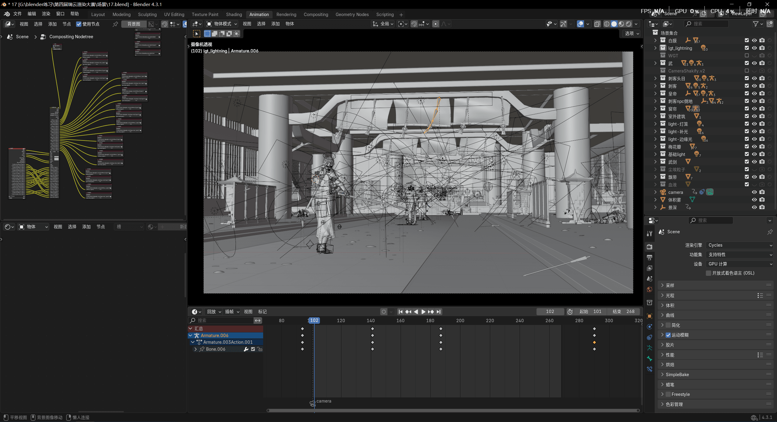
For jewelers seeking a powerful, completely free 3D modeling software, Blender stands unparalleled. This open-source powerhouse offers a formidable suite of tools that rival expensive competitors. Its exceptional sculpting capabilities allow for the creation of intricate, organic forms and detailed wax-carving-like models that are difficult to achieve in other programs. 

Coupled with its robust rendering engine, Cycles, Blender enables you to create stunning, photorealistic presentations of your jewelry without any additional software costs. While its interface has a steeper learning curve and it lacks some jewelry-specific automation, its immense flexibility, active global community, and zero financial barrier make it the best free software for ambitious designers willing to invest time to master its vast potential.

Blender制作画面2.jpg


ZBrush: 3D Design Software for High-end Jewelry 
For jewelry designers who prioritize organic, sculptural artistry, ZBrush is the industry's digital wax carver. It is unparalleled in its ability to produce high-quality poly work using its extensive range of brushes, allowing you to intuitively sculpt intricate details, textures, and complex geometries as if working with a physical material. A key advantage of jewelry is its ability to create incredibly realistic-looking models that are not polygon-heavy, optimizing them perfectly for 3D printing without sacrificing detail. This makes it exceptional for designing intricate pieces like signet rings, nature-inspired motifs, and detailed talismans. 

While not free, its specialized power for organic creation makes it an indispensable tool for bringing high-end, artistic jewelry visions to life with digital precision. It is very extensive and therefore requires time to learn it well and use its full capabilities, but this is such a small disadvantage against the background of many advantages.

ZBrush


SketchUp: Best 3D Jewelry Design Software for Beginners
For jewelers who need to quickly visualize an idea or create a presentable mock-up for a client, SketchUp is an excellent tool for rapid 3D design. Its greatest strength is its intuitive, user-friendly interface, which makes it incredibly quick to mock up to-scale drawings and geometric forms. While not as precise as NURBS-based software for final manufacturing, it excels at producing high-resolution models that are great for quick renderings and presentations. 

It is easy to add color and materials, and its extensive warehouse of extensions allows you to create surprisingly realistic renderings with minimal effort. The integration of new AI features further streamlines this process, generating polished presentation images in seconds. For speed and visual communication over technical fabrication, SketchUp is a highly effective choice.

The Best 3D Software for Interior Design-SketchUp


Tinkercad: Best Jewelry Design Software for Beginners
If you're a jewelry designer new to the world of 3D modeling and printing, Tinkercad is the perfect platform to begin your journey. Designed with absolute beginners in mind, it requires no complex software installation and runs directly from your web browser. Its intuitive, drag-and-drop interface allows you to quickly combine primitive shapes like rings, tubes, and gems to construct your designs without a steep learning curve. 

Within a very short time, you can effortlessly translate your creative ideas into tangible, workable 3D models ready for casting or printing. Tinkercad removes the technical intimidation, letting you focus purely on bringing your unique jewelry concepts to life.

TinkerCAD


Fox Renderfarm: From Design to Render: Bringing Your Jewelry to Life
Once your stunning 3D jewelry design is complete, the next step is bringing it to life through photorealistic rendering—a process that demands significant computational power. This is where Fox Renderfarm excels. As a leading cloud rendering service, Fox Renderfarm provides the powerful, scalable resources needed to transform your complex Rhino, ZBrush, or Blender scenes into high-resolution images and animations without overwhelming your local computer. Their platform is optimized for all the major software and plugins discussed, ensuring compatibility and a streamlined workflow.

By handling the heavy processing in the cloud, Fox Renderfarm drastically reduces rendering times from hours to minutes, freeing you to continue designing. For jewelers, this means you can rapidly iterate on presentation materials, create breathtaking client visuals, and produce marketing assets with incredible speed and professional quality. It is the indispensable final tool for taking your meticulous digital craftsmanship and presenting it in its absolute best light.

task-overview.png


FAQ about Jewelry Modeling and Design Software
What is the industry standard for jewelry design?
The industry standard for jewelry design is Rhino 3D (Rhinoceros), particularly with the Matrix or Goldsmith plugins. This combination is dominant because it offers unparalleled precision for complex organic shapes and intricate details required for high-quality pieces. Its powerful NURBS-based modeling tools are specifically tailored for creating manufacturable designs for casting, making it the preferred choice for professional jewelers and master model makers.

Which software has the best tools for rings settings?
For dedicated ring setting tools, RhinoGold (a plugin for Rhino) is widely considered the best. It offers an extensive library of pre-designed, parametric settings for prongs, bezels, channels, and pavé, allowing for incredibly fast and precise creation. Its tools are specifically built for jewelry manufacturing, ensuring settings are structurally sound and ready for casting and stone setting.

Sum Up
Your journey to find the right 3D jewelry design software ends by matching a tool to your specific goals, skill level, and budget. Whether you choose the precision of Rhino, the artistry of ZBrush, the power of Blender, or the simplicity of Tinkercad, each program offers a unique path to bring your ideas to life.

Once your design is ready, bring it to life with photorealistic renders. Fox Renderfarm is a powerful cloud-based render farm that integrates seamlessly with all major design software. It drastically cuts rendering times from hours to minutes, allowing you to create high-resolution, stunning visuals without being limited by your computer's power. This lets you iterate faster and present your work with flawless quality, ensuring your digital creations are presented perfectly.

Interested

How to Create the Entrance of 'For Honor'
The leading cloud rendering service provider and render farm in the CG industry, Fox Renderfarm, will show you in this post a scene inside "For Honor," the Entrance, created by a student who is learning 3D modeling. The creator completed this work over a period of four weeks by solving problems and challenges with the help of his/her teacher and his/her own efforts. This article is a summary of his/her experience in the creation of this scene.Final result:Analyzing Concept Art &x26; Building Rough ModelsThis is a case of the PBR workflow, specifically utilizing 3ds Max for low-poly modeling, ZBrush for high-poly sculpting, TopoGun for retopology, Substance Painter and Photoshop for texture, and ultimately rendering with Marmoset Toolbag 4.To ensure production progress, in the early stages, the scene was initially constructed in 3ds Max based on the concept art as a large-scale reference for proportions, and then the actual production process began.Rough modelMaking Mid-poly ModelsHouse Structure: serving as the foundation of the scene framework. The house was divided into several parts for construction, including the roof, walls, floor, door frames, steps, and two side stone platforms. Through analyzing the concept art, it was determined that the stone walls and roof tiles employ a repeating texture pattern, which was subsequently applied throughout the scene.The scene props included stone lion statues, lanterns, ropes of hanging tassels, and more. Among them, the stone statues, steps, and several wooden elements were sculpted using ZBrush.The process of creating the mid-poly model involved continuously refining and adding more intricate details based on the rough model. It was important to analyze which models require sculpting and retopology during the initial stages of production, and which models could be reduced in detail to serve as the low-poly model. Conducting this analysis early on significantly improved efficiency in the production process.Mid-poly modelMaking High-poly ModelsThe high-poly modeling stage was relatively intense, involving numerous wooden doors, plaques, walls, as well as stone steps and statues. However, the task became less laborious when it came to identical wooden boards in the scene, as they could be easily adjusted and reused.Statue sculpting:Since the only element in this scene that required complete sculpting was the stone lion, I decided to challenge and improve my sculpting skills by starting from a sphere. After several days of sculpting, I began to see some progress. Then, with guidance from my teacher, I delved deeper into proportions, structure, and finer details.Props sculpting:The wooden boards, during the sculpting process, were meticulously sculpted stroke by stroke to enhance the texture and bring out the grain. Additionally, props like stone steps were also carved.Afterward, the UV unwrapping and baking process followed.Making Low-poly ModelsIn the early stages, we conducted an analysis of the assets. Among them, only the stone lion required retopology, while the remaining props could be obtained through reducing the mesh of mid-poly models.Overall, retopologizing the low-poly model is a relatively simple but patient task. There are several points to consider during the process: 1. Controlling the polygon count of the model. 2. Planning the mesh topology in a logical manner and determining whether certain details need to be retopologized. 3. Evaluating the density of the mesh topology for proper distribution.During the low-poly retopology stage, we encountered few difficulties. We followed a standard of 1m³/512 pixels to create the textures and planned them accordingly based on the predetermined pixel density. Then, we proceeded with UV unwrapping and layout. Throughout this process, we encountered issues such as seams appearing and models turning black. Eventually, we identified the problems as certain areas of the model lacking smooth group separation in the UVs and flipped normals. When placing the UVs, it is important to fully utilize the UV space to avoid wasting resources. Additionally, we needed to redo some of the UV work later on. It should be noted that in 3ds Max, when using automatic smoothing groups, it may not be apparent if the normals are flipped. Therefore, it is advisable to double-check after completing each section.Next was the normal map baking. We matched the high-poly and low-poly models in 3ds Max and ensured that there was some distance between all the models to avoid overlapping during the baking process. If any issues arose with the baked normals, we would repair them in Photoshop. Fortunately, there were no major problems throughout the entire baking process, so minor adjustments in Photoshop were sufficient.Low-poly modelMaking MaterialsI initially conducted material rendering for the sculpture and showed it to my teacher. However, the teacher pointed out some shortcomings. With guidance from the teacher, I gained a new understanding of material rendering. The key is to focus on volume first and then details. Volume here does not solely refer to the presence of volume under lighting conditions, but also the perception of volume even in the absence of lighting, relying only on colors. The addition of darker shades and textures further enhances the sense of volume in the model. Finally, sharpening was performed to make the details more prominent. By following this approach, the materials created would appear three-dimensional under lighting effects.RenderingAfter completing meticulous file organization, I standardized the naming of models, material spheres, and textures. This significantly reduced the workload when using Marmoset Toolbag 4. Once all the preparations were done, I began placing the models, setting up the lighting, adding special effects, and finally positioning the camera for rendering. During this process, a considerable amount of time was spent on lighting. The coordination between model materials and lighting never seemed to achieve the desired effect. However, with guidance from my teacher, I was able to improve the overall result.The above is our experience sharing the production process of the Entrance for the game "For Honor".Source: Thepoly
More
2023-09-28
Learn How to Make a Handheld Fan in 3D
Today, Fox Renderfarm, the industry's leading cloud rendering service provider and render farm, will bring you a 3D tutorial that explains how to make a handheld fan. Let's get started right now.First import the image, use the straight line tool to draw the length of the handle, then use the rotational molding tool to create the handle and add a cover.Generate a rectangle using the center point, adjust it to the appropriate size, and then generate a circular runway. At this point, use the fitting tool to get the appropriate shape.Select the circular runway that was just generated, hold down Shift to extrude the faces on both sides and add a cover, then use the shell tool to shell both sides.Copy the inner edge line of the shell, extrude the face and add the cover, pull off the inner face to keep only the outer side, and then chamfer to generate the outer layer of the shell that needs to be hollowed out.Use curves to draw the edge shape of the connecting axis, then use rotational molding to generate the surface, and then add the cover to generate the solid.Connect the rectangle diagonal, use the diagonal to generate a round tube, and adjust the angle and thickness of the tube so that the angle and thickness of the tube match the reference picture.Draw a diagonal line again and use the Line Array tool to array along this line, where the number of arrays is 18.Use the object intersection line function to select the round tube and the shell to be hollowed out, determine whether the position matches by the object intersection line, adjust the position and then cut to get the hollowed out object.Use the Rectangle tool to generate a runway circle, adjust it to the right size, then cut and combine it with the hollow object and offset it inward to get the solid. The same can be done for the outer runway circle, here you need to make a copy of the hollow object for backup.Use the mirror tool to mirror the hollowed-out model made in the previous step to the back, then use the method in the fourth step to get an unhollowed-out shell, generate a rounded rectangle and cut it according to the second reference picture, then use the combination tool to combine, and finally offset the surface to get the solid.Use a rectangle to frame the size of the button, then use a straight line to connect the midpoint of the rectangle, next use the center point tool to generate a circle, and squeeze the circle to the right size and adjust the height of the button.Split the button and the handle for spare, and then chamfer the top of the handle for the next step.For the base, again using the rotational molding tool. First draw the edge shape using curves, then rotate the shape and cap it to create a solid.Now perform the Boolean split between the handle and the base, then detach the surface. Next, copy the edge line, move the inner circle downwards, use the double rail sweep to generate the surface and combine it to obtain the base shape.Use the center point circle and rectangle tools to generate the button and indicator light shapes on the handle, extrude the solid and then perform a boolean split with the handle to get the handle shape and the indicator light.Use the Rectangle to create the runway circle and rotate it 45° to get the "x" below, then use the Trim tool to trim off the excess lines and combine them. After extruding the surface, use the Boolean split tool to split it to get the "x" icon.Now create the circular texture on the button. First abstract the structure line to get a button-sized circle, then generate a circle solid at the circle node, and use the Array Along Curve tool to make an array. Arrange the five columns in sequence according to the image and mirror them to get the desired texture. Finally, we use Boolean split to get the button shape.Chamfer the intersection of the button and the handle, and chamfer the intersection of the handle and the base.Use the curve to draw the fan shape, then use the XN tool to generate the surface, and array along the center point. The number of arrays here is 5. Adjust the fan blade position and extrude the fan blade solid.Check the model and chamfer it to complete the model.The next step is to render the product. First, divide the product into four layers, one for the orange object, one for the flesh-colored object, one for the metal connection, and one for the self-illumination. Then start rendering.First adjust the model position by aligning the model to the ground in the Advanced Options.Set the model materials to the model in turn. Note that you need to turn down the metallic shine of the metal joints in order to get a frosted look.Adjust the self-luminous material on the handle to the right intensity in accordance with the light, and choose white as the color.Set the setting options in the image to Press Exposure, High Contrast, and Photography.Change the background color in the environment settings. Use the straw tool to absorb the image color, turn down the brightness of one light in the HDR editor, hit the light on the hollow surface, adjust the shape of the light to rectangle, and then hit a main light on the left side of the product to make a shadow appear on the right side.Adjust the object position in the camera, lock the camera, and finish the rendering.Source: YBW
More
2023-07-20
How to Use VFace and Make Effects in Arnold?
In this article, Fox Renderfarm, the CG industry's leading cloud rendering service provider and render farm, will share with you how to use VFace and how to restore effects in the Arnold renderer. The author is CaoJiajun.Firstly I purchased some VFace materials from the official website to get the following files.We will mainly use the above files for this sharing, they are our main materials to make high quality details of the face. VFace provides 2 types of facial models, one for the head with open eyes and one for the head with closed eyes, choose one of them according to your needs. If you are doing a model that needs to be animated with expressions in post, I would recommend choosing the model with closed eyes, as the open eyes model will cause the eyelids to stretch when you do the blink animation. You don't need to worry about this for still-frame work.Let's start with the production process. It's actually very simple, wrap your own model with a VFace model through Wrap or Zwrap, then pass the map and finally render it in Maya or other 3D software. The process is simple but there will be a lot of things that need to be taken care of in there otherwise the facial details will not be rendered correctly.1 Model CleaningFirst we need to load the model provided by VFace into ZBrush and match it to our sculpted model.Then you can head into Zwrap or Wrap for wrapping.Lastly, the wrapped model is imported into ZBrush to replace the VFace model.In ZBrush we use the Project brush to match the face of the wrapped model more precisely to our own sculpted model, once matched you will have a model that matches your sculpted model perfectly, at this point we can go into Mari for the map transfer.2 Using Mari to Transfer the MapIn Mari we first set up the project, import our own sculpted model or the wrapped and matched XYZ model, then remove the other channels in the Channels and keep only the Basecolor channel, and we can customize the channels as we wish.What we see now is how the model looks when imported into Mari. At this point we need to set the custom channels DIFF\DISP\UNITY\ to import the VFace map.Firstly, the DIFF channel is set at the original size of 16k and the Depth is set at 16bit (later on there can be more color depth control and of course it can be set to 8bit). The key point is that when the color depth is set to 16bit or 32bit, the color space needs to be set to linear and 8bit to srgb.Keep the size of displacement map at 16k. I recommend setting the Depth to 32bit, as you will get more detail of displacement, and keep the color space linear, with Scalar Data ticked (as the displacement map is a color map with 3 channels of RGB, you need to keep the greyscale data).The blend map settings are the same as the color map, but Scalar Data also needs to be ticked (this map is used as a color mask for toning or as a weighting mask).Next we can use the object panel to append our own model in preparation for the transfer of the map.Right-click on any channel and select the Transfer command in the pop-up menu to bring up the menu for transferring the map.In the transfer menu select the channel which needs to be transferred in the first step, set the transfer object in the second step, click on the arrow in the third step, set the size in the fourth step and finally click on the ok button.I generally recommend passing one channel at a time as it is very slow and takes a long time to wait. For size I usually choose 4k for color, 8k for displacement and 4k for mixing channels. This step requires a lot of patience!VFace original effectThe effect after transferAfter the transfer we can export the map. The export map settings are shown in the figure. We need to pay attention to the color space setting (in the red box). The color space of the color channel is set to linear and should also be set to linear when exporting. The export of displacement and hybrid maps is a bit more unusual, as we set the color space to linear when creating the channel, but the export needs to be set to srgb, as both the displacement and hybrid maps are a combination of the 3 channels R,G,B to form a color map. Finally click the export button and it's done.VFace original color effectColor effects after exportingVFace original displacementEffect after exportIn short, your output map needs to be the same color as the map provided by VFace, either too bright or too dark is an error.3 Arnold RenderingDefault settingsAt this point we can go to Maya and render the VFace map we have created (we won't go into the lighting environment and materials here, we will focus on the link to the replacement map). First we import the passed VFace map and render it by default to see what we get. Obviously we get an ugly result, so how to set it to get it right?Here we add an aisubtract node (which you can interpret as a subtraction or exclusion node), because the default median value of VFace is 0.5 and arnold prefers a replacement map with a median value of 0. So we enter the VFace color into input1 and change the color of input2 to a luminance value of 0.5. This is equivalent to subtracting the 0.5 luminance info from the default 0.5 median luminance of VFace, and we get a displacement with a median value of 0.Median value 0.5Median value 0After setting the median we can add an aimultply node. This node can be interpreted as a multiplyDivide node, which has the same function as Maya's own multiplyDivide node and controls the overall strength of the VFace displacement. We can output the color of the aisubract node to the input1 node of aimultply and adjust the overall strength of the detail displacement of VFace by using the black, grey and white of input2 (any value multiplied by 1 equals 1, any value multiplied by 0 equals 0, all the colors we can see in the computer are actually numbers to the computer. We can change the value and thus the strength of the map by simple mathematical calculations, once we know this we can see why we use the multiplyDivide node to control the strength of the displacement).Next we add an ailayerRgba node. The R, G and B channels of the aimultipy are connected to the R channels of input1, 2 and 3 of ailayerRgba, and through the mix attribute of this node we can control the intensity of the displacement of each of the three VFace channels (R, G and B), and after a series of settings we can get a correct and controlled rendering of the VFace displacement.VFace-dispZBrush-dispVFace+ZBrush dispZBrush Export Displacement SettingsAlthough we have a correct and controlled VFace displacement result, it does not combine with the displacement we sculpted in Zbrush and we need to find a way to combine the two to get our final displacement effect.Here I used the aiAdd node to add the two displacement maps together to get our VFace displacement + ZBrush displacement effect (of course you can also use Maya's plusMinus node).It doesn't matter how many displacement map elements you have (such as the scar on the face, etc.), you can structure them through the aiAdd node to get a composite displacement effect. The advantage of making it this way is that you can adjust the strength and weakness of each displacement channel at any time, without having to import and export them in different software. It is a very standard linear process approach.Default effectAfter color correctionFinally we apply the passed color to the subsurface color, and by default we get a very dark color mapping, which is not wrong. The VFace default model will be the same color. We can correct the skin color by using the hue, saturation and lightness of the colourCorrect node. This is why I choose 16bit colors to bake with, so I can get more control over the colors and get a correct result after color correction (of course the current result is just a rough mapping, we can still do deeper work on the map to get a better result).As a powerful render farm offering arnold cloud rendering services, Fox Renderfarm hopes this article can give you some help.Source: Thepoly
More
2023-07-19
Business Consulting

Global Agent Contact: Evan Zhang

Email: evan.zhang@foxrenderfarm.com

Marketing Contact: Evan Liu

Email: evanliu@foxrenderfarm.com

Message Us:
Newsletter
Keep up with our latest software updates, special offers and events!
Copyright © 2025 FoxRenderfarm.com. All Rights Reserved.