Up To 40% Bonus On Your First Rechargeclose

Ambient Occlusion: What It Is, How It Works, and When to Use It

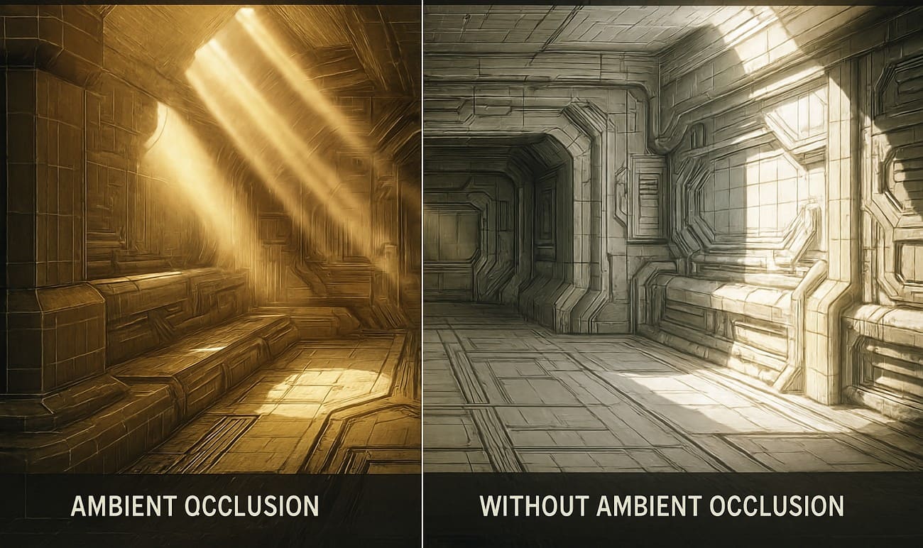
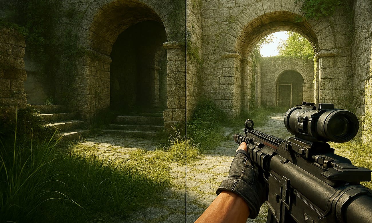
Have you ever seen 3D objects look flat or fake, even under full light? This happens because scenes can miss subtle contact shadows in areas where light barely reaches. In this case, the ambient occlusion will resolve this issue by introducing depth and authenticity to each scene.

It adds gentle shading in tight areas and keeps open surfaces brighter, which makes scenes feel more natural. This tutorial describes what ambient occlusion is, how it functions, and why and where it is best applied to sharpen and enhance the realism of the 3D images you create.

ambient occlusion definition


Part 1. What is Ambient Occlusion in 3D Graphics?

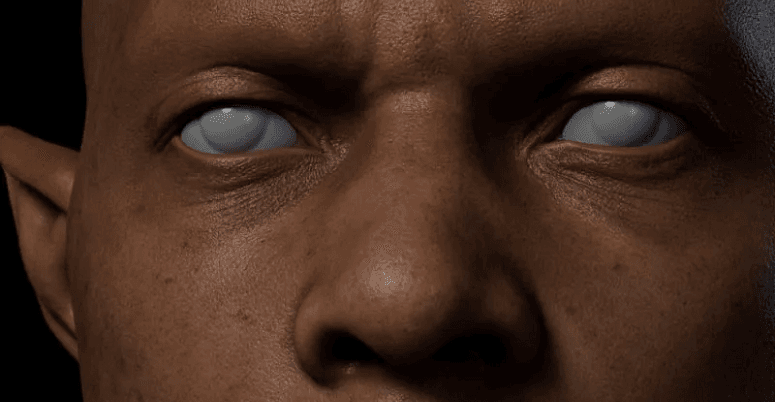
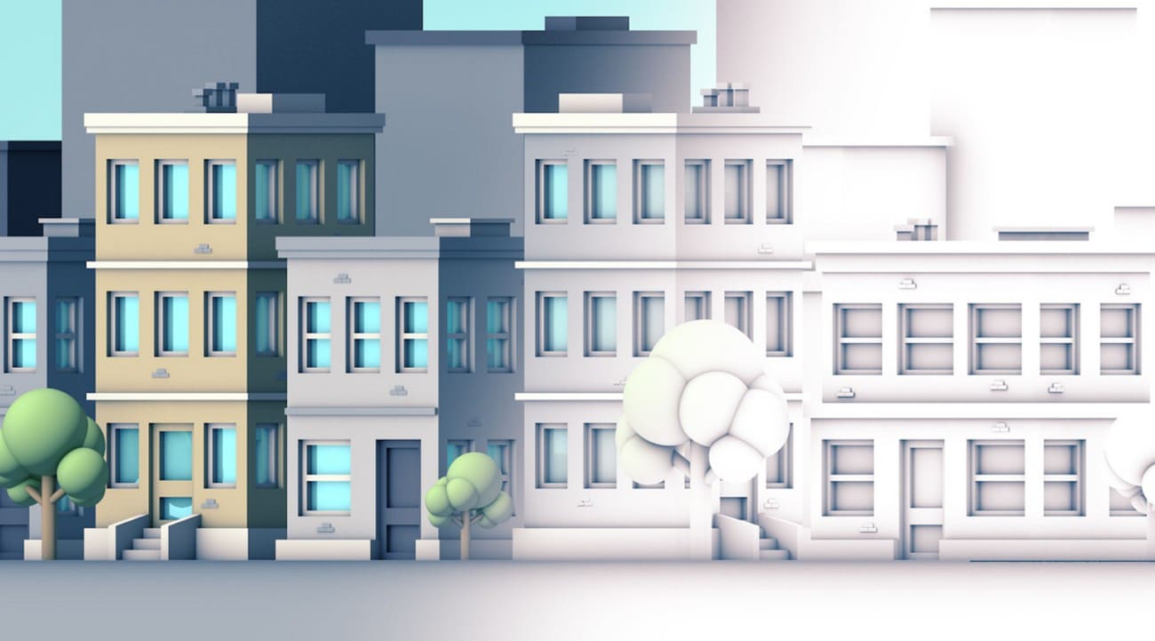
Ambient occlusion is a shading method in 3D graphics that darkens corners, creases, and tight spaces where light cannot reach. This makes models and scenes look more real and three-dimensional without heavy rendering. It stops scenes from looking flat and grounds objects naturally.

ambient occlusion definition

Besides, ambient occlusion is cheaper than full global illumination, so it is common in games, visualizations, and VFX to improve realism at low cost. Plus, it often works with physically based materials to highlight edges, panel gaps, fabric folds, and brick joints. Artists usually keep the effect subtle, and a strong AO appears artificial or unnatural, whereas a light touch adds natural depth and realism.


Part 2. How Does Ambient Occlusion Work?

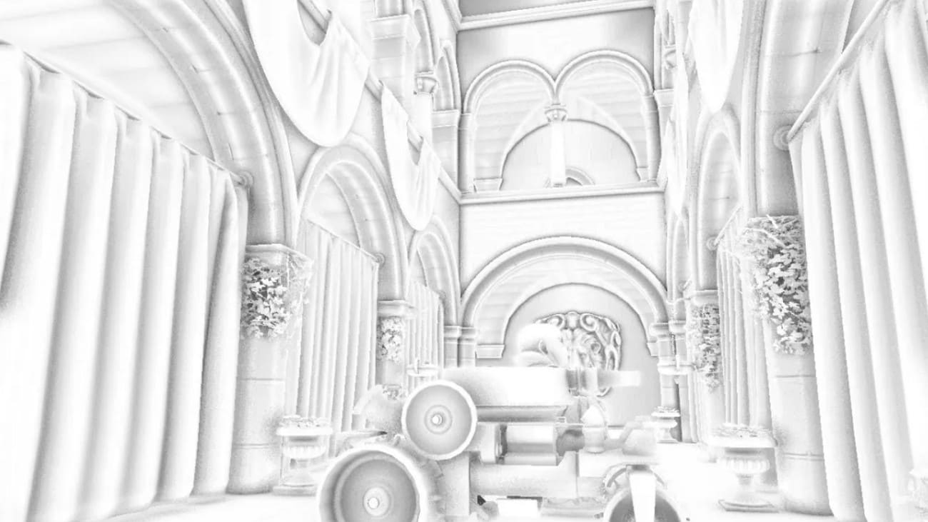
To understand its effect, you may ask, what does ambient occlusion do? It creates soft shadows in corners, creases, and tight spaces where light cannot reach. This gives 3D models and scenes more depth, making them look realistic. Areas blocked by nearby objects appear darker, while open surfaces remain bright, adding natural contrast without heavy rendering.

ambient occlusion working

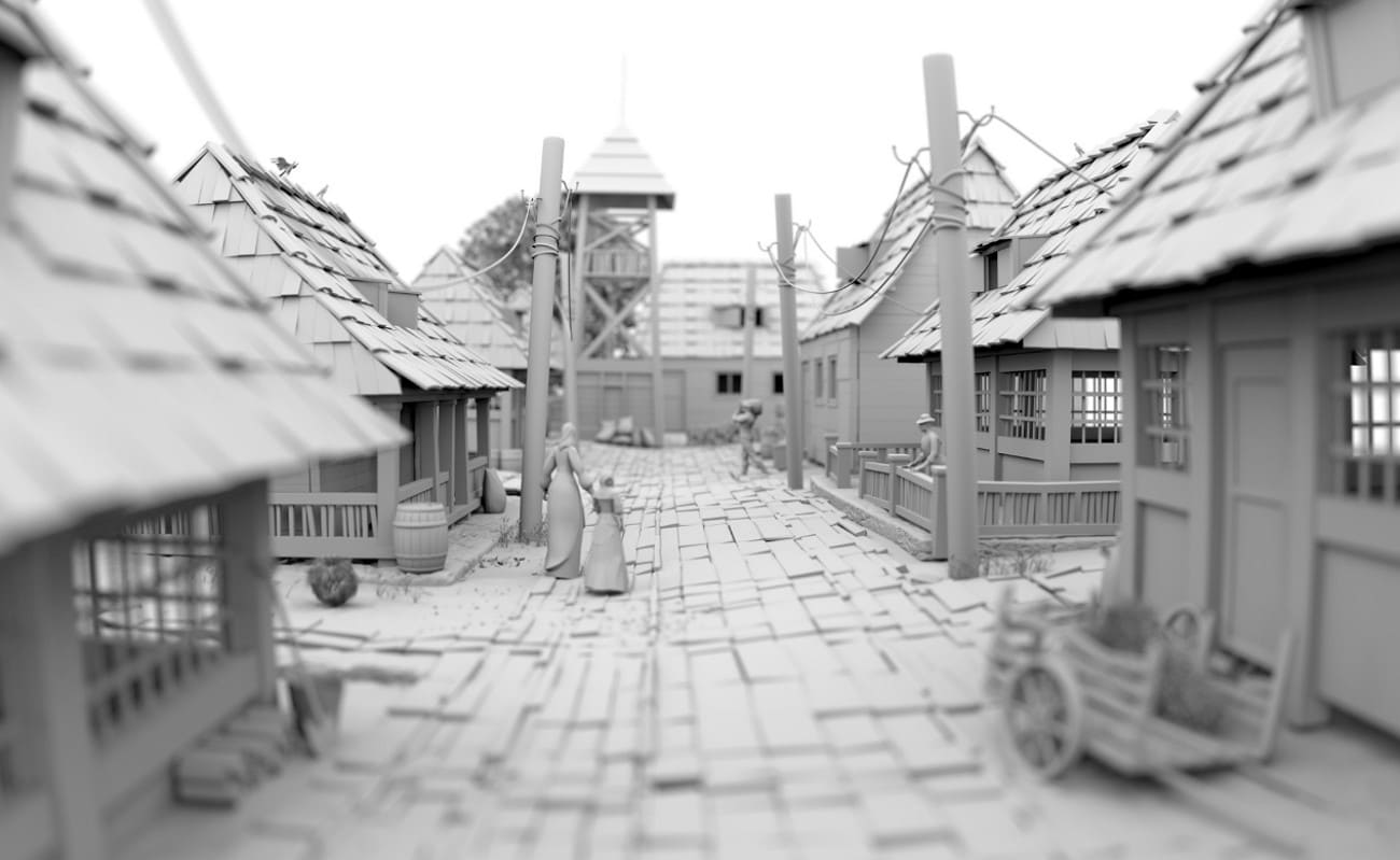
Core Principle and Computation Steps

The system calculates how much ambient light reaches each point by checking multiple directions around it. So, the fraction of blocked light forms an occlusion factor, which reduces light in cramped areas and keeps open areas bright. 

Screen-Space Ambient Occlusion (SSAO)

In real-time graphics, Screen Space Ambient Occlusion uses depth and normal from the rendered image to create fast, realistic shadows. This enhances visual detail while keeping performance cost low.


Part 3. What is the Difference Between Ambient Occlusion and Global Illumination?

Both in computer graphics, ambient occlusion and global illumination help to render a 3D scene more realistic by displaying the effects of light on surfaces. Global illumination simulates indirect light bounces across a scene, while ambient occlusion only estimates how much ambient light is blocked in corners and tight surface areas.

ambient occlusion and global illumination

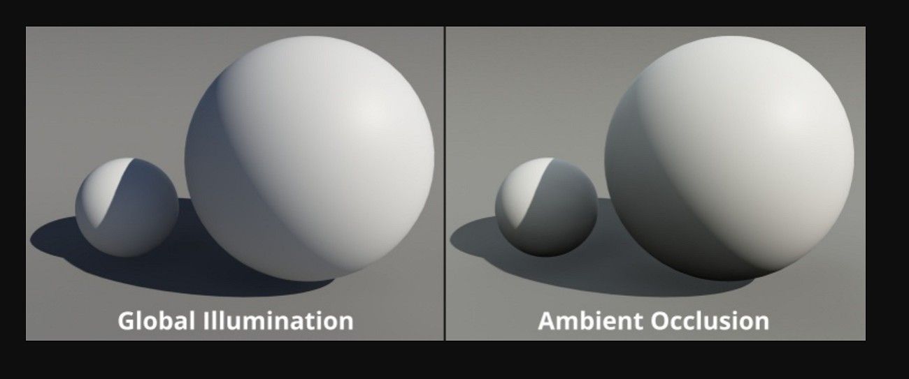
Light occlusion in ambient occlusion provides soft shadows along corners, creases, and tight spaces, providing depth and a more three-dimensional appearance to objects. Ambient occlusion is faster and simpler, while global illumination gives full, realistic lighting but requires more computation.

What Does Ambient Occlusion Do?

Ambient occlusion darkens corners, creases, and tight spaces where ambient light cannot reach. It does not simulate full light bounces but only changes how much ambient light reaches a point, adding soft shadows that give depth and contrast. Besides, it does not create color bleeding or real indirect light like global illumination.

What Does Global Illumination Do?

Global iIllumination models full light transport across a scene, including indirect bounces, reflections, refractions, and diffusion, depending on the renderer. It takes indirect light, softened shadows, and color bleeding to render scenes realistic. It also attempts to reproduce light in the real world on the entire scene, usually by techniques such as path tracing or radiosity, light probes, or baked global illumination.

Key Differences at a Glance

Aspect

Ambient Occlusion (AO)

Global Illumination (GI)

Main Purpose

Enhance depth via soft contact shadows in occluded areas.

Simulate full indirect lighting and light transport in the scene.


What It Models

How much ambient light is blocked locally.

How light bounces, spreads, and changes color globally.

Light Bounces

No real bounces; just darkening.

Multiple bounces and interactions between surfaces.

Visual Effects

Local soft shadows increase under objects and in corners.

Indirect light, color bleeding, soft global shadows, and overall light balance.

Cost & Usage

Relatively cheap; widely used in games as a post-effect.


More expensive; common in films, archviz, and higher‑end or hybrid game renderers

How They Work Together

Ambient occlusion is often applied on top of global illumination to add light occlusion in corners and creases that global illumination may miss. Additionally, ambient occlusion complements global illumination by enhancing small details rather than replacing it.
 

Part 4. What are the Different Types of Ambient Occlusion?

Ambient occlusion has several types that differ by calculation method and cost. Some types suit offline work, while others suit real-time use. Most fall into two main groups: baked AO for static scenes and real-time AO methods, such as screen space, voxel, or ray-traced ambient occlusion. These options balance visual quality and performance based on project needs.

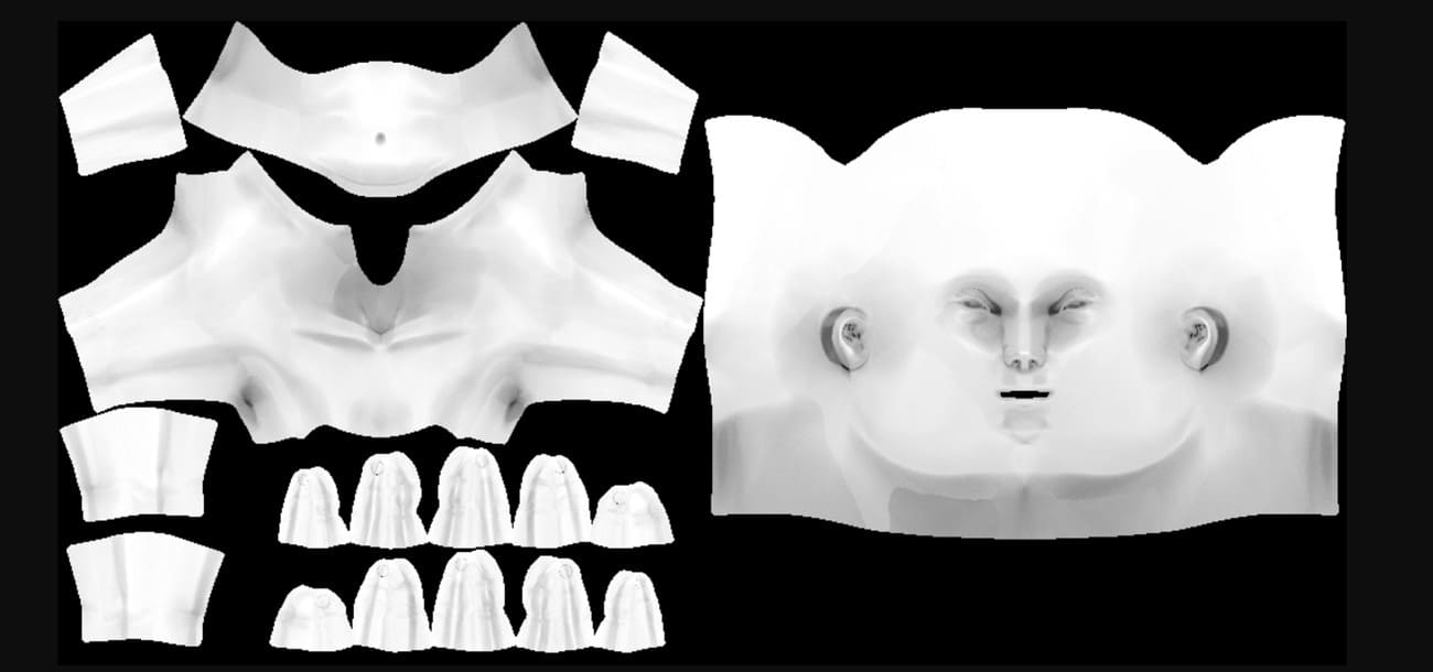
1. Baked/Precomputed Ambient Occlusion

Baked/Precomputed ambient occlusion is calculated offline and saved in textures or vertex colors. During render time, the system applies it to the material to add depth. This method suits static objects and scenes, such as buildings and props. It costs very little at runtime and provides stable, high-quality contact shadows.

ambient occlusion baked type

2. Screen Space Ambient Occlusion (SSAO)

Screen Space Ambient Occlusion is the original standard where ambient occlusion uses depth and normal data from the rendered frame. It checks nearby pixels to darken corners and creases. Ambient occlusion in games often uses SSAO because it works in real time as a post-process. It may look noisy or less accurate, since it only uses what appears on screen.

ambient occlusion ssao type

3. Horizon‑/High‑Definition Ambient Occlusion (HBAO/HDAO)

HBAO (NVIDIA) and HDAO (AMD) are advanced SSAO methods that use better sampling and greater detail for smoother, more accurate occlusion. They produce softer and cleaner shadows than basic SSAO but use more GPU power, so games often offer them as optional graphics settings.

ambient occlusion hbao and hdao


4. Voxel Ambient Occlusion (VXAO)

VXAO turns scene geometry into a 3D voxel grid to estimate how ambient light is blocked, even by objects outside the screen. It looks more realistic than SSAO and feels closer to full global effects, but it uses much more power, so only a few high-end games use it.

ambient occlusion vxao type

5. Ground‑Truth/Ray‑Traced Ambient Occlusion (GTAO / RTAO)

Ground-Truth Ambient Occlusion (GTAO) and Ray-Traced Ambient Occlusion (RTAO) use more realistic sampling or hardware ray tracing to produce accurate ambient occlusion. These methods respect true scene geometry and reduce visual artifacts, but they require more computation and usually appear in modern engines with ray tracing support.

ambient occlusion ground truth type


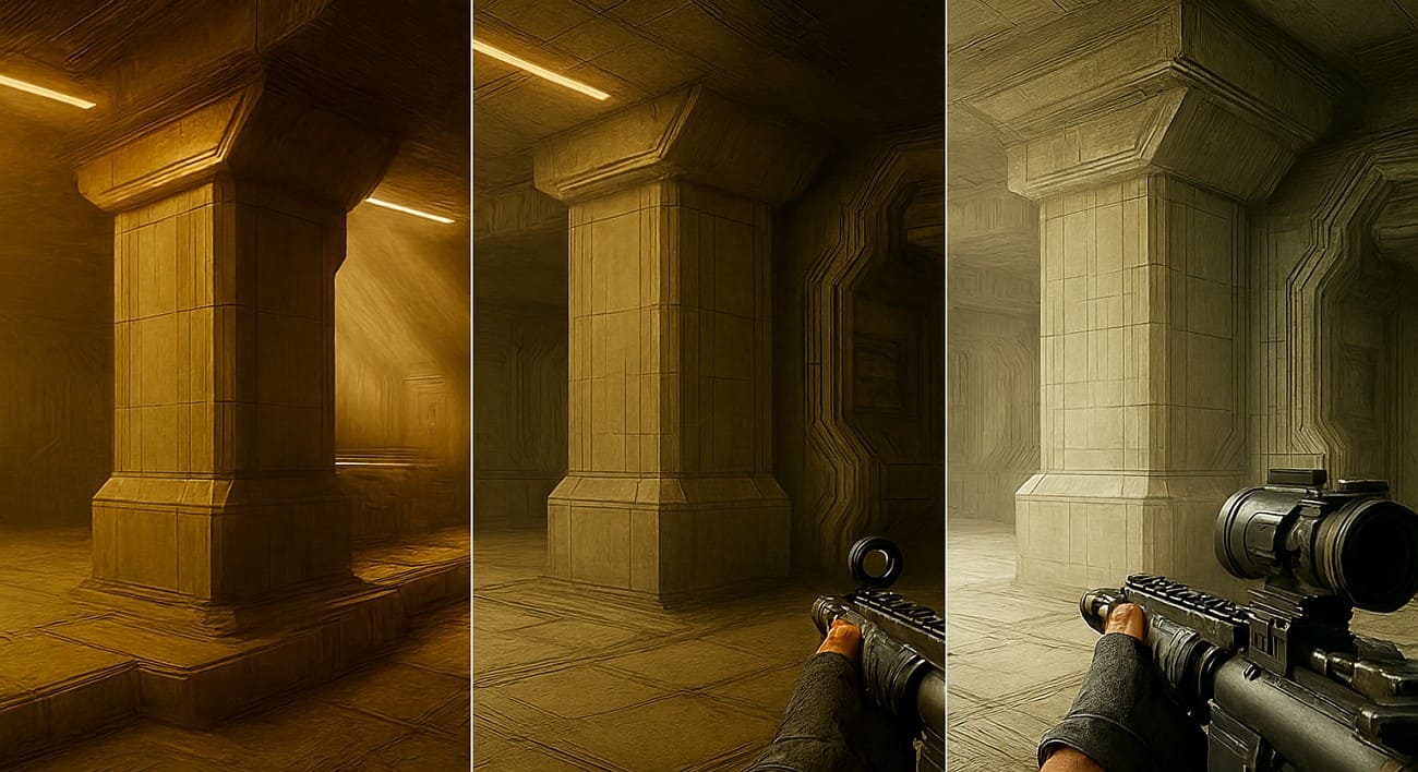
Part 5. Should You Turn Ambient Occlusion On or Off?

Turn Ambient Occlusion on if you want better depth and more realistic visuals, and your system can handle a small performance drop. On the other hand, turn it off or lower it if you need higher FPS or if the effect looks too dark or noisy.

ambient occlusion on or off

When to Turn Ambient Occlusion On?

Many players prefer this effect in single-player or cinematic games. Ambient occlusion adds soft shadows in corners and where objects touch, which makes scenes look more realistic and less flat. On mid-to-high-end GPUs, the performance drop is often acceptable, around 10-20 FPS in some games. As a result, users usually keep AO on and lower the less noticeable settings instead.

When to Turn Ambient Occlusion off or Too Low?

Competitive players often turn it off to keep frame rates high and controls responsive. Ambient occlusion can cost a lot of performance, especially at high resolutions like 4K, sometimes reducing 10–20 FPS or more. Low-quality or very strong AO can look blotchy or unnatural and may reduce visibility in dark areas. In such cases, turning it off or using a lower, cleaner option makes sense.

Practical recommendation - The "Middle Ground"

  • In single-player or visually detailed games, keep ambient occlusion on Medium or High if your FPS remains smooth.

  • For competitive or performance-focused games, set ambient occlusion to Low or Off, and only enable it if you have plenty of FPS to spare.


Part 6. How is Ambient Occlusion Used in Practice?

Ambient occlusion is used in many fields to add subtle occlusion shadows, depth, and realism without the high cost of full global illumination. How ambient occlusion is applied depends on the content type: real-time use in games or VR/AR, and offline use in film or architectural visualization.

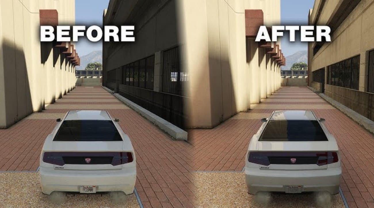
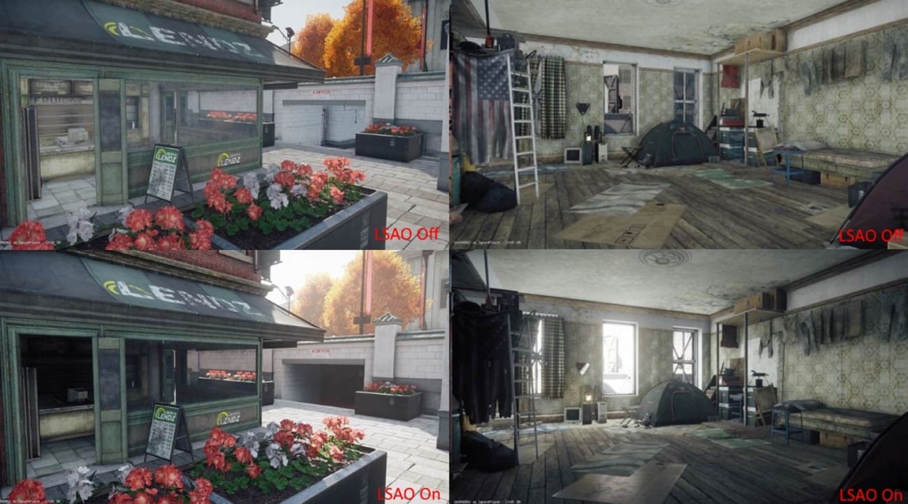
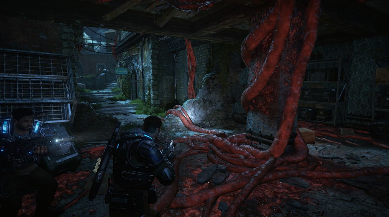
1. Ambient Occlusion in Games

Games usually use screen space ambient occlusion to add shadows in corners, creases, and contact points in real time. This makes worlds look less flat and more realistic. AO appears as a graphics option so players can choose better depth at some cost to performance. It is most noticeable around rocks, foliage, character armor, and objects inside buildings.

ambient occlusion in games

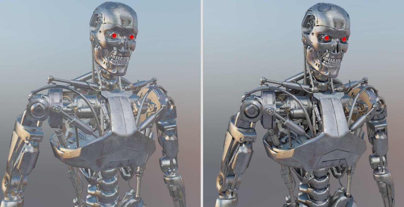
2. Ambient Occlusion in 3D Rendering and Animation

In offline rendering for film and animation, ambient occlusion is baked into textures or used as a separate render pass to add material detail and occlusion shadows. Artists add the AO pass to the main render to show folds, gaps, and small surface details like wrinkles, screws, or panel lines. This makes the final image more realistic and detailed.

ambient occlusion in animation

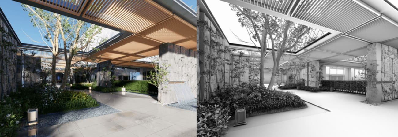
3. Ambient Occlusion in Architectural Visualization

Architectural visualization artists apply ambient occlusion to highlight connections between walls, floors, furniture, window frames, and exterior details. This helps interiors and exteriors appear solid and realistic rather than floating.

It passes, or maps, are often combined with the main image in Photoshop or similar software to add subtle shadows in corners and edges. This improves contrast and gives still images a natural, photographic feel without complex light calculations.

ambient occlusion in architectural visualization

4. Ambient Occlusion in VR and AR

In VR and AR, ambient occlusion improves the perception of depth and space in virtual scenes while keeping performance costs low. It creates realism without full light calculations. Developers use light AO methods, like optimized SSAO or baked AO, so objects in VR training, product demos, and AR displays appear fixed to surfaces. This makes virtual scenes feel stable, natural, and believable.

ambient occlusion in vr


Part 7. How to Optimize Ambient Occlusion Without Losing Quality?

Ambient occlusion can be improved by choosing smart methods, adjusting settings, and using a render farm to keep depth and realism without slowing performance.

1. Pick the Right Ambient Occlusion Method

For real-time work, use efficient methods like SSAO or HBAO+ instead of heavy AO, such as VXAO or ray-traced AO, unless you have high-end hardware. SSAO and HBAO give a good balance of quality and speed, while ray-traced AO is best for premium presets.

choose ambient occlusion method

2. Use Render Farm

Heavy ambient occlusion with high samples or detailed passes can be slow on a single machine. In this case, a render farm could help. Fox Renderfarm processes AO maps or frames on many computers at once, keeping high resolution and clean shadows while reducing total render time. This is useful for large scenes like cities, interiors, or product showcases.

choose fox render farm

3. Adjust Samples, Radius, and Intensity

Lower ambient occlusion samples slightly and add a subtle blur to reduce noise. Keep the radius moderate and intensity low to medium. Too strong AO looks dirty and wastes GPU power.

4. Use Lower-Resolution AO with Filtering

Compute ambient occlusion at lower resolution, then upscale and blur it. Limit AO to certain areas, such as interiors or dark regions, to save performance.

use lower ambient occlusion

5. Bake AO for Static Content

For static objects, bake AO into textures or vertex colors. This provides high-quality shadows at runtime without extra cost.


Part 8. FAQs about Ambient Occlusion

1. Is Ambient Occlusion necessary?

It is not strictly necessary, but ambient occlusion adds depth and realism to scenes. It helps objects feel grounded and less flat.

2. Does Ambient Occlusion increase FPS?

No, ambient occlusion usually reduces FPS slightly because it adds extra calculations. Lowering AO settings or turning it off can improve performance.

3. Is Ambient Occlusion CPU or GPU?

Ambient occlusion mainly uses the GPU for real-time effects in games. Some offline AO calculations can use the CPU for baking.


Conclusion

Summing up, Ambient Occlusion adds depth and realism to 3D scenes by creating soft shadows in corners, creases, and contact points. Proper AO choice and optimization keep visuals sharp without heavy performance loss. For high-quality renders, especially with heavy AO passes or animations, using an online solution like Fox Renderfarm ensures fast, clean results while maintaining full detail.

Interested

How to Create the Entrance of 'For Honor'
The leading cloud rendering service provider and render farm in the CG industry, Fox Renderfarm, will show you in this post a scene inside "For Honor," the Entrance, created by a student who is learning 3D modeling. The creator completed this work over a period of four weeks by solving problems and challenges with the help of his/her teacher and his/her own efforts. This article is a summary of his/her experience in the creation of this scene.Final result:Analyzing Concept Art &x26; Building Rough ModelsThis is a case of the PBR workflow, specifically utilizing 3ds Max for low-poly modeling, ZBrush for high-poly sculpting, TopoGun for retopology, Substance Painter and Photoshop for texture, and ultimately rendering with Marmoset Toolbag 4.To ensure production progress, in the early stages, the scene was initially constructed in 3ds Max based on the concept art as a large-scale reference for proportions, and then the actual production process began.Rough modelMaking Mid-poly ModelsHouse Structure: serving as the foundation of the scene framework. The house was divided into several parts for construction, including the roof, walls, floor, door frames, steps, and two side stone platforms. Through analyzing the concept art, it was determined that the stone walls and roof tiles employ a repeating texture pattern, which was subsequently applied throughout the scene.The scene props included stone lion statues, lanterns, ropes of hanging tassels, and more. Among them, the stone statues, steps, and several wooden elements were sculpted using ZBrush.The process of creating the mid-poly model involved continuously refining and adding more intricate details based on the rough model. It was important to analyze which models require sculpting and retopology during the initial stages of production, and which models could be reduced in detail to serve as the low-poly model. Conducting this analysis early on significantly improved efficiency in the production process.Mid-poly modelMaking High-poly ModelsThe high-poly modeling stage was relatively intense, involving numerous wooden doors, plaques, walls, as well as stone steps and statues. However, the task became less laborious when it came to identical wooden boards in the scene, as they could be easily adjusted and reused.Statue sculpting:Since the only element in this scene that required complete sculpting was the stone lion, I decided to challenge and improve my sculpting skills by starting from a sphere. After several days of sculpting, I began to see some progress. Then, with guidance from my teacher, I delved deeper into proportions, structure, and finer details.Props sculpting:The wooden boards, during the sculpting process, were meticulously sculpted stroke by stroke to enhance the texture and bring out the grain. Additionally, props like stone steps were also carved.Afterward, the UV unwrapping and baking process followed.Making Low-poly ModelsIn the early stages, we conducted an analysis of the assets. Among them, only the stone lion required retopology, while the remaining props could be obtained through reducing the mesh of mid-poly models.Overall, retopologizing the low-poly model is a relatively simple but patient task. There are several points to consider during the process: 1. Controlling the polygon count of the model. 2. Planning the mesh topology in a logical manner and determining whether certain details need to be retopologized. 3. Evaluating the density of the mesh topology for proper distribution.During the low-poly retopology stage, we encountered few difficulties. We followed a standard of 1m³/512 pixels to create the textures and planned them accordingly based on the predetermined pixel density. Then, we proceeded with UV unwrapping and layout. Throughout this process, we encountered issues such as seams appearing and models turning black. Eventually, we identified the problems as certain areas of the model lacking smooth group separation in the UVs and flipped normals. When placing the UVs, it is important to fully utilize the UV space to avoid wasting resources. Additionally, we needed to redo some of the UV work later on. It should be noted that in 3ds Max, when using automatic smoothing groups, it may not be apparent if the normals are flipped. Therefore, it is advisable to double-check after completing each section.Next was the normal map baking. We matched the high-poly and low-poly models in 3ds Max and ensured that there was some distance between all the models to avoid overlapping during the baking process. If any issues arose with the baked normals, we would repair them in Photoshop. Fortunately, there were no major problems throughout the entire baking process, so minor adjustments in Photoshop were sufficient.Low-poly modelMaking MaterialsI initially conducted material rendering for the sculpture and showed it to my teacher. However, the teacher pointed out some shortcomings. With guidance from the teacher, I gained a new understanding of material rendering. The key is to focus on volume first and then details. Volume here does not solely refer to the presence of volume under lighting conditions, but also the perception of volume even in the absence of lighting, relying only on colors. The addition of darker shades and textures further enhances the sense of volume in the model. Finally, sharpening was performed to make the details more prominent. By following this approach, the materials created would appear three-dimensional under lighting effects.RenderingAfter completing meticulous file organization, I standardized the naming of models, material spheres, and textures. This significantly reduced the workload when using Marmoset Toolbag 4. Once all the preparations were done, I began placing the models, setting up the lighting, adding special effects, and finally positioning the camera for rendering. During this process, a considerable amount of time was spent on lighting. The coordination between model materials and lighting never seemed to achieve the desired effect. However, with guidance from my teacher, I was able to improve the overall result.The above is our experience sharing the production process of the Entrance for the game "For Honor".Source: Thepoly
More
2023-09-28
Learn How to Make a Handheld Fan in 3D
Today, Fox Renderfarm, the industry's leading cloud rendering service provider and render farm, will bring you a 3D tutorial that explains how to make a handheld fan. Let's get started right now.First import the image, use the straight line tool to draw the length of the handle, then use the rotational molding tool to create the handle and add a cover.Generate a rectangle using the center point, adjust it to the appropriate size, and then generate a circular runway. At this point, use the fitting tool to get the appropriate shape.Select the circular runway that was just generated, hold down Shift to extrude the faces on both sides and add a cover, then use the shell tool to shell both sides.Copy the inner edge line of the shell, extrude the face and add the cover, pull off the inner face to keep only the outer side, and then chamfer to generate the outer layer of the shell that needs to be hollowed out.Use curves to draw the edge shape of the connecting axis, then use rotational molding to generate the surface, and then add the cover to generate the solid.Connect the rectangle diagonal, use the diagonal to generate a round tube, and adjust the angle and thickness of the tube so that the angle and thickness of the tube match the reference picture.Draw a diagonal line again and use the Line Array tool to array along this line, where the number of arrays is 18.Use the object intersection line function to select the round tube and the shell to be hollowed out, determine whether the position matches by the object intersection line, adjust the position and then cut to get the hollowed out object.Use the Rectangle tool to generate a runway circle, adjust it to the right size, then cut and combine it with the hollow object and offset it inward to get the solid. The same can be done for the outer runway circle, here you need to make a copy of the hollow object for backup.Use the mirror tool to mirror the hollowed-out model made in the previous step to the back, then use the method in the fourth step to get an unhollowed-out shell, generate a rounded rectangle and cut it according to the second reference picture, then use the combination tool to combine, and finally offset the surface to get the solid.Use a rectangle to frame the size of the button, then use a straight line to connect the midpoint of the rectangle, next use the center point tool to generate a circle, and squeeze the circle to the right size and adjust the height of the button.Split the button and the handle for spare, and then chamfer the top of the handle for the next step.For the base, again using the rotational molding tool. First draw the edge shape using curves, then rotate the shape and cap it to create a solid.Now perform the Boolean split between the handle and the base, then detach the surface. Next, copy the edge line, move the inner circle downwards, use the double rail sweep to generate the surface and combine it to obtain the base shape.Use the center point circle and rectangle tools to generate the button and indicator light shapes on the handle, extrude the solid and then perform a boolean split with the handle to get the handle shape and the indicator light.Use the Rectangle to create the runway circle and rotate it 45° to get the "x" below, then use the Trim tool to trim off the excess lines and combine them. After extruding the surface, use the Boolean split tool to split it to get the "x" icon.Now create the circular texture on the button. First abstract the structure line to get a button-sized circle, then generate a circle solid at the circle node, and use the Array Along Curve tool to make an array. Arrange the five columns in sequence according to the image and mirror them to get the desired texture. Finally, we use Boolean split to get the button shape.Chamfer the intersection of the button and the handle, and chamfer the intersection of the handle and the base.Use the curve to draw the fan shape, then use the XN tool to generate the surface, and array along the center point. The number of arrays here is 5. Adjust the fan blade position and extrude the fan blade solid.Check the model and chamfer it to complete the model.The next step is to render the product. First, divide the product into four layers, one for the orange object, one for the flesh-colored object, one for the metal connection, and one for the self-illumination. Then start rendering.First adjust the model position by aligning the model to the ground in the Advanced Options.Set the model materials to the model in turn. Note that you need to turn down the metallic shine of the metal joints in order to get a frosted look.Adjust the self-luminous material on the handle to the right intensity in accordance with the light, and choose white as the color.Set the setting options in the image to Press Exposure, High Contrast, and Photography.Change the background color in the environment settings. Use the straw tool to absorb the image color, turn down the brightness of one light in the HDR editor, hit the light on the hollow surface, adjust the shape of the light to rectangle, and then hit a main light on the left side of the product to make a shadow appear on the right side.Adjust the object position in the camera, lock the camera, and finish the rendering.Source: YBW
More
2023-07-20
How to Use VFace and Make Effects in Arnold?
In this article, Fox Renderfarm, the CG industry's leading cloud rendering service provider and render farm, will share with you how to use VFace and how to restore effects in the Arnold renderer. The author is CaoJiajun.Firstly I purchased some VFace materials from the official website to get the following files.We will mainly use the above files for this sharing, they are our main materials to make high quality details of the face. VFace provides 2 types of facial models, one for the head with open eyes and one for the head with closed eyes, choose one of them according to your needs. If you are doing a model that needs to be animated with expressions in post, I would recommend choosing the model with closed eyes, as the open eyes model will cause the eyelids to stretch when you do the blink animation. You don't need to worry about this for still-frame work.Let's start with the production process. It's actually very simple, wrap your own model with a VFace model through Wrap or Zwrap, then pass the map and finally render it in Maya or other 3D software. The process is simple but there will be a lot of things that need to be taken care of in there otherwise the facial details will not be rendered correctly.1 Model CleaningFirst we need to load the model provided by VFace into ZBrush and match it to our sculpted model.Then you can head into Zwrap or Wrap for wrapping.Lastly, the wrapped model is imported into ZBrush to replace the VFace model.In ZBrush we use the Project brush to match the face of the wrapped model more precisely to our own sculpted model, once matched you will have a model that matches your sculpted model perfectly, at this point we can go into Mari for the map transfer.2 Using Mari to Transfer the MapIn Mari we first set up the project, import our own sculpted model or the wrapped and matched XYZ model, then remove the other channels in the Channels and keep only the Basecolor channel, and we can customize the channels as we wish.What we see now is how the model looks when imported into Mari. At this point we need to set the custom channels DIFF\DISP\UNITY\ to import the VFace map.Firstly, the DIFF channel is set at the original size of 16k and the Depth is set at 16bit (later on there can be more color depth control and of course it can be set to 8bit). The key point is that when the color depth is set to 16bit or 32bit, the color space needs to be set to linear and 8bit to srgb.Keep the size of displacement map at 16k. I recommend setting the Depth to 32bit, as you will get more detail of displacement, and keep the color space linear, with Scalar Data ticked (as the displacement map is a color map with 3 channels of RGB, you need to keep the greyscale data).The blend map settings are the same as the color map, but Scalar Data also needs to be ticked (this map is used as a color mask for toning or as a weighting mask).Next we can use the object panel to append our own model in preparation for the transfer of the map.Right-click on any channel and select the Transfer command in the pop-up menu to bring up the menu for transferring the map.In the transfer menu select the channel which needs to be transferred in the first step, set the transfer object in the second step, click on the arrow in the third step, set the size in the fourth step and finally click on the ok button.I generally recommend passing one channel at a time as it is very slow and takes a long time to wait. For size I usually choose 4k for color, 8k for displacement and 4k for mixing channels. This step requires a lot of patience!VFace original effectThe effect after transferAfter the transfer we can export the map. The export map settings are shown in the figure. We need to pay attention to the color space setting (in the red box). The color space of the color channel is set to linear and should also be set to linear when exporting. The export of displacement and hybrid maps is a bit more unusual, as we set the color space to linear when creating the channel, but the export needs to be set to srgb, as both the displacement and hybrid maps are a combination of the 3 channels R,G,B to form a color map. Finally click the export button and it's done.VFace original color effectColor effects after exportingVFace original displacementEffect after exportIn short, your output map needs to be the same color as the map provided by VFace, either too bright or too dark is an error.3 Arnold RenderingDefault settingsAt this point we can go to Maya and render the VFace map we have created (we won't go into the lighting environment and materials here, we will focus on the link to the replacement map). First we import the passed VFace map and render it by default to see what we get. Obviously we get an ugly result, so how to set it to get it right?Here we add an aisubtract node (which you can interpret as a subtraction or exclusion node), because the default median value of VFace is 0.5 and arnold prefers a replacement map with a median value of 0. So we enter the VFace color into input1 and change the color of input2 to a luminance value of 0.5. This is equivalent to subtracting the 0.5 luminance info from the default 0.5 median luminance of VFace, and we get a displacement with a median value of 0.Median value 0.5Median value 0After setting the median we can add an aimultply node. This node can be interpreted as a multiplyDivide node, which has the same function as Maya's own multiplyDivide node and controls the overall strength of the VFace displacement. We can output the color of the aisubract node to the input1 node of aimultply and adjust the overall strength of the detail displacement of VFace by using the black, grey and white of input2 (any value multiplied by 1 equals 1, any value multiplied by 0 equals 0, all the colors we can see in the computer are actually numbers to the computer. We can change the value and thus the strength of the map by simple mathematical calculations, once we know this we can see why we use the multiplyDivide node to control the strength of the displacement).Next we add an ailayerRgba node. The R, G and B channels of the aimultipy are connected to the R channels of input1, 2 and 3 of ailayerRgba, and through the mix attribute of this node we can control the intensity of the displacement of each of the three VFace channels (R, G and B), and after a series of settings we can get a correct and controlled rendering of the VFace displacement.VFace-dispZBrush-dispVFace+ZBrush dispZBrush Export Displacement SettingsAlthough we have a correct and controlled VFace displacement result, it does not combine with the displacement we sculpted in Zbrush and we need to find a way to combine the two to get our final displacement effect.Here I used the aiAdd node to add the two displacement maps together to get our VFace displacement + ZBrush displacement effect (of course you can also use Maya's plusMinus node).It doesn't matter how many displacement map elements you have (such as the scar on the face, etc.), you can structure them through the aiAdd node to get a composite displacement effect. The advantage of making it this way is that you can adjust the strength and weakness of each displacement channel at any time, without having to import and export them in different software. It is a very standard linear process approach.Default effectAfter color correctionFinally we apply the passed color to the subsurface color, and by default we get a very dark color mapping, which is not wrong. The VFace default model will be the same color. We can correct the skin color by using the hue, saturation and lightness of the colourCorrect node. This is why I choose 16bit colors to bake with, so I can get more control over the colors and get a correct result after color correction (of course the current result is just a rough mapping, we can still do deeper work on the map to get a better result).As a powerful render farm offering arnold cloud rendering services, Fox Renderfarm hopes this article can give you some help.Source: Thepoly
More
2023-07-19
Business Consulting

Global Agent Contact: Evan Zhang

Email: evan.zhang@foxrenderfarm.com

Marketing Contact: Evan Liu

Email: evanliu@foxrenderfarm.com

Message Us:
Newsletter
Keep up with our latest software updates, special offers and events!
Copyright © 2026 FoxRenderfarm.com. All Rights Reserved.