30% Bonus On your First Rechargeclose

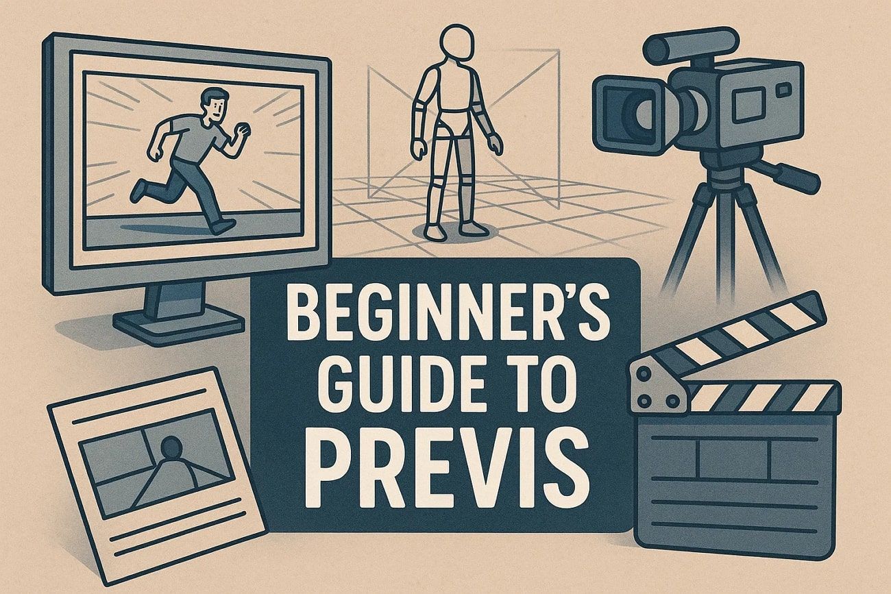
A Beginner’s Guide to Previsualization for Film and Animation

Many beginners in film and animation struggle to bring their ideas to life clearly. They often waste time adjusting the screen, camera angles, or timing during production. This is where previsualization solves the problem and lets creators plan scenes before filming or final animation. Since previs might be new for some beginners, this guide provides an extensive guide to previsualization for film and animation. 

what is previsualization


Part 1. What Is Pre-Visualization?

Pre-visualization, or called Previs, is a process used in film and animation to plan scenes before production. It helps creators see how shots, camera angles, and sequences will look. For that, it creates a rough version of the scenes, and filmmakers can make decisions early, avoid mistakes, and save time and money.

overview of previsualization

Above all, previs can be done with simple sketches, storyboards, or basic digital tools. It also helps the entire team understand the vision and work together more effectively.


Part 2. 5 Common Types of Previsualization

Know that previsualization features various types, and some of them are explained below for better clarity: 
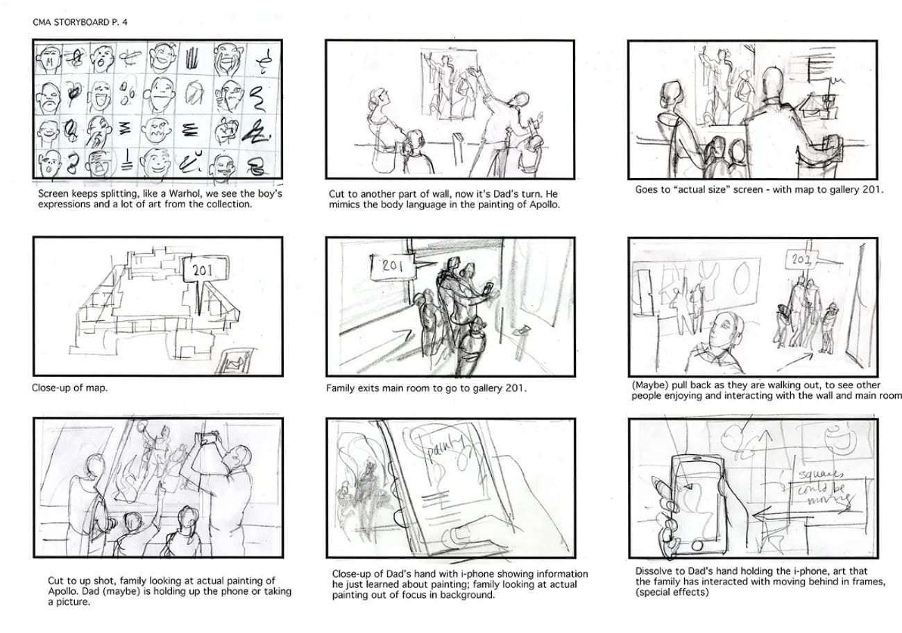
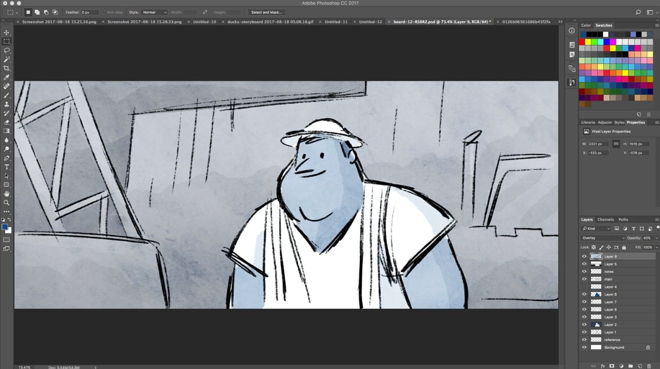
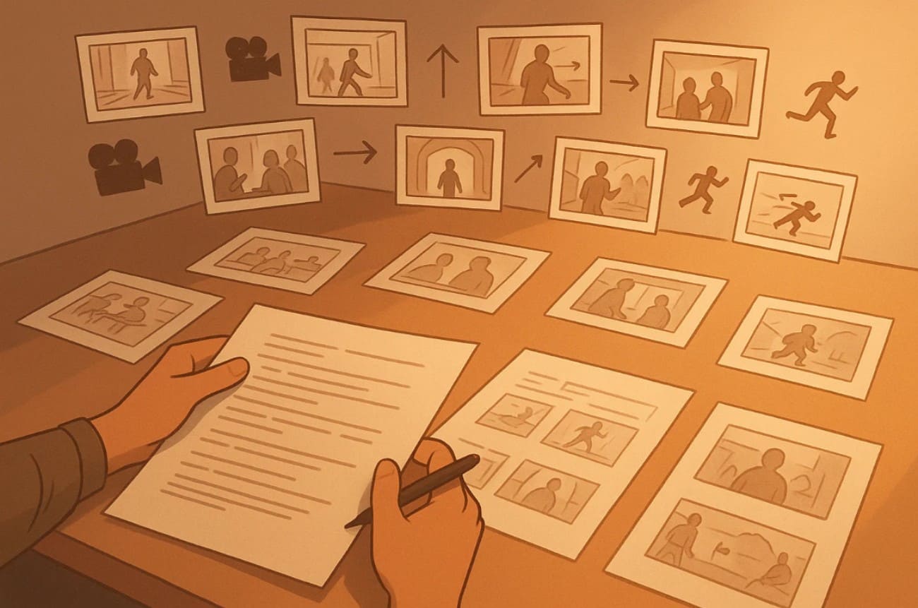
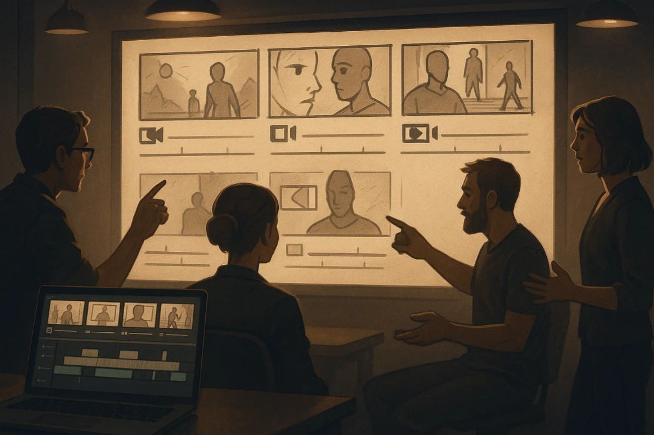
1. Storyboards

Storyboards are a series of drawings or frames that show important moments and camera angles. They usually contain straightforward drawings with comments or captions. There are also concept arts and mood boards, which reveal the appearance, style, and feel of a scene. Storyboards communicate lighting, color, and setting prior to technical planning and assist the team to adopt the visuals and mood of the film or animation.
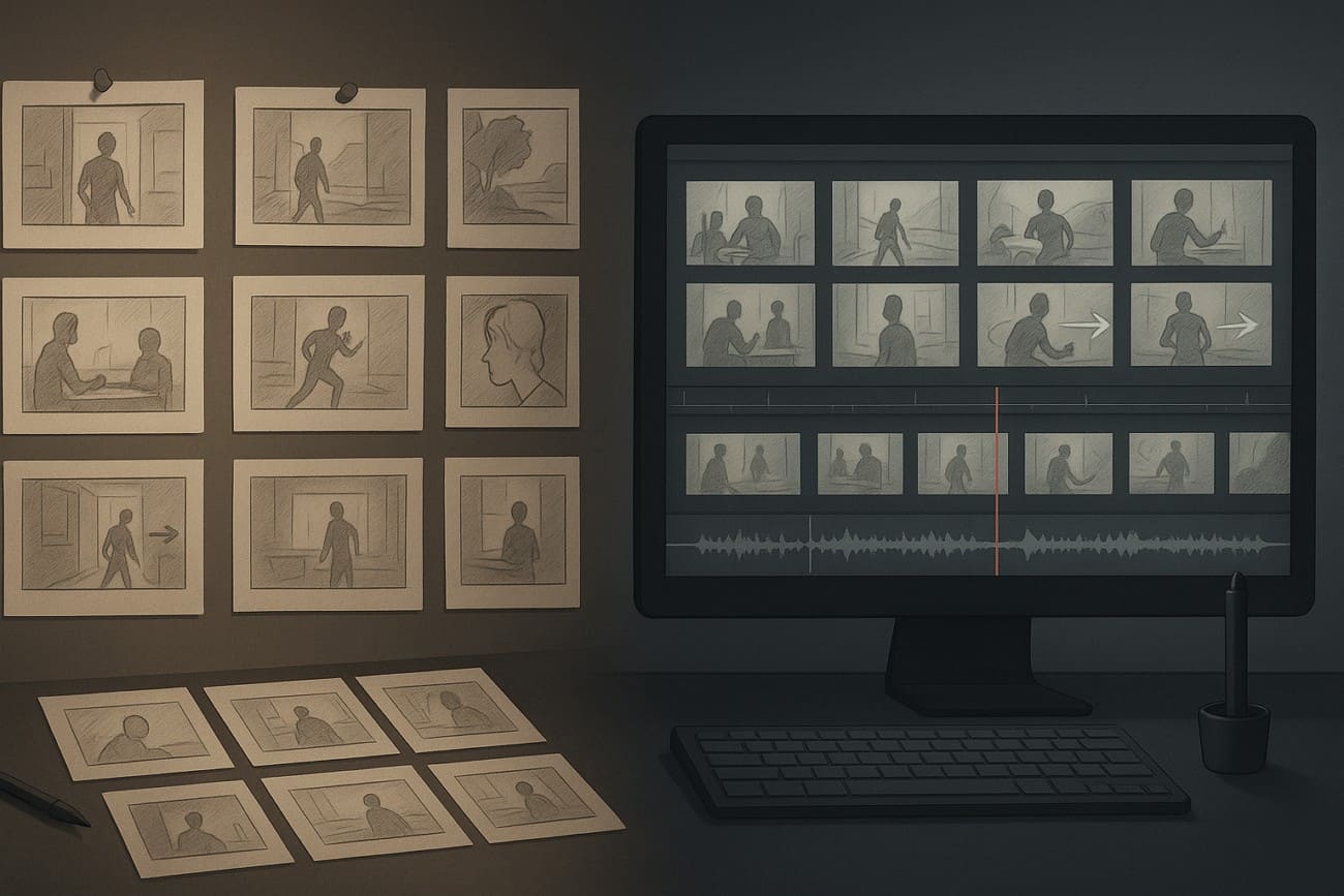
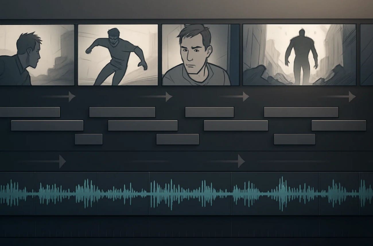
previsualization type storyboard

2. Animatic

As you learn about previs definition, know that an Animatic is a short video made from storyboard frames, rough artwork, temporary sound, and dialogue. This kind of previsualization shows how a scene flows, the rhythm of shots, and timing before expensive 3D or live action work. Hence, directors and editors can see the pacing and order of shots and make changes early.
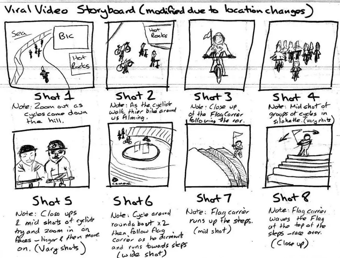
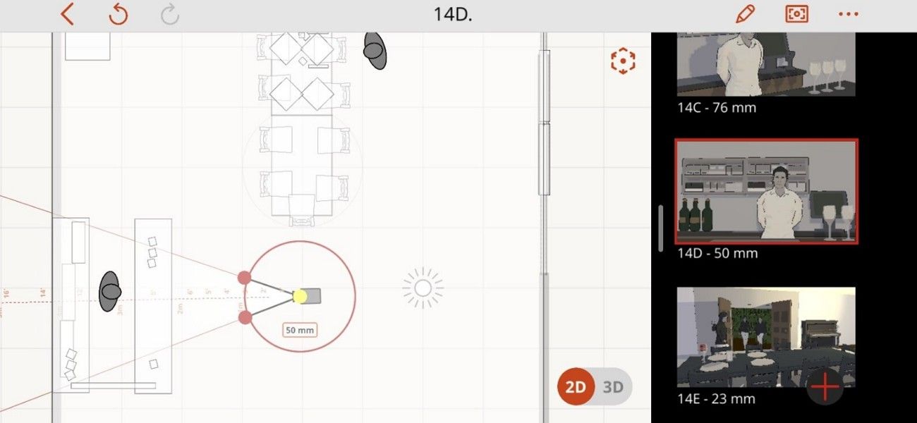
previsualization type animatic

3. Shot list

Shot list is used to plan all shots in a scene before production and involves creating a detailed list of every camera shot, angle, and framing. Every shot normally contains the kind of shot, position of the camera, choice of lens, and any kind of movement or activity. 

Therefore, this kind of previs is a process to assist the director, cinematographer, and crew as they know what to shoot, nothing is missed, and time is saved on the set.
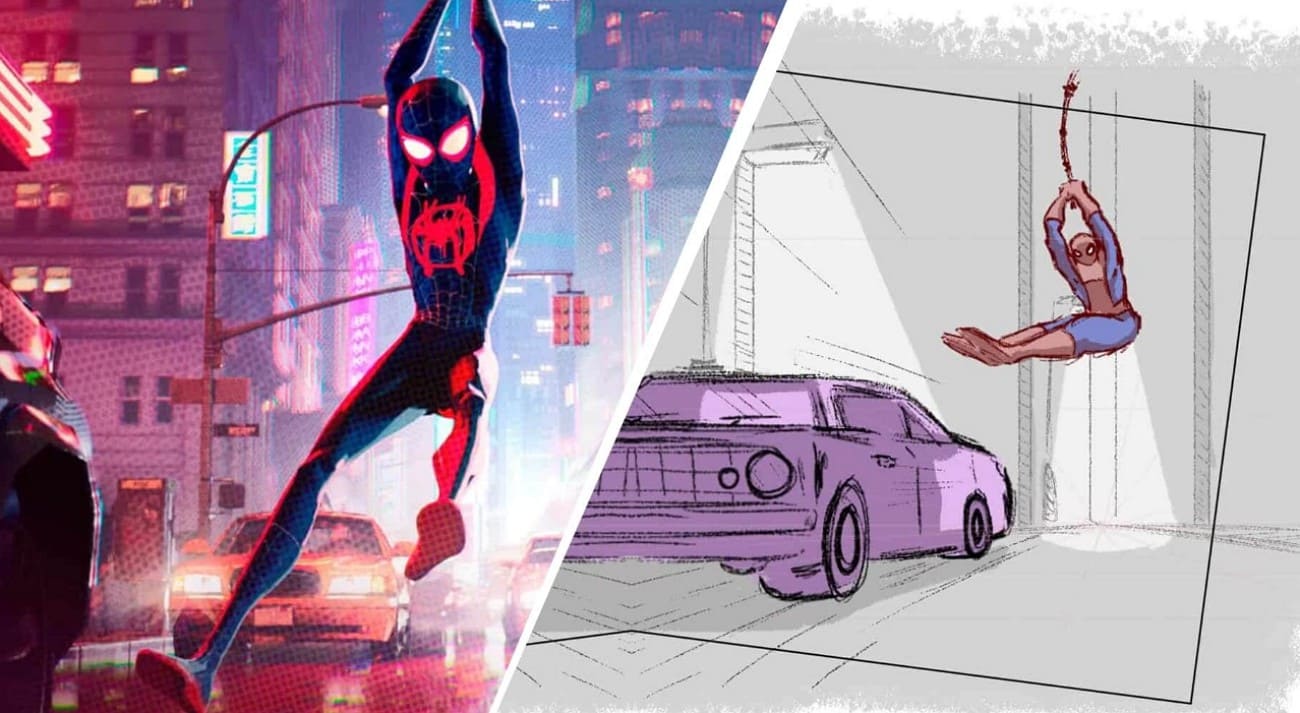
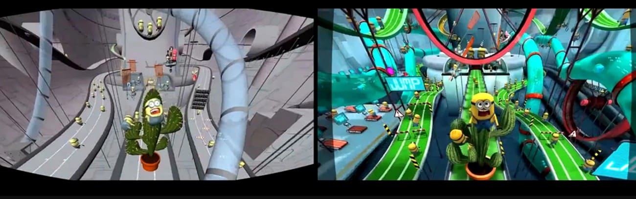
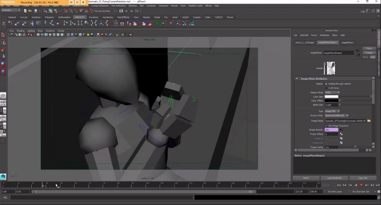
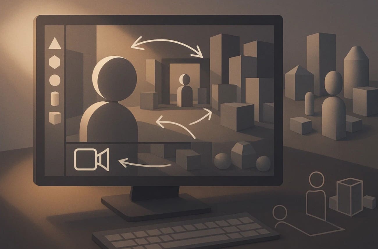
previsualization type shot list

4. 3D Previs

3D previs uses simple 3D models, cameras, and virtual sets to plan movement, camera paths, and complex action. It allows the team to test lens choices, scene layout, and interactions of effects. Thus, this creates precise storyboards and shot lists for production.
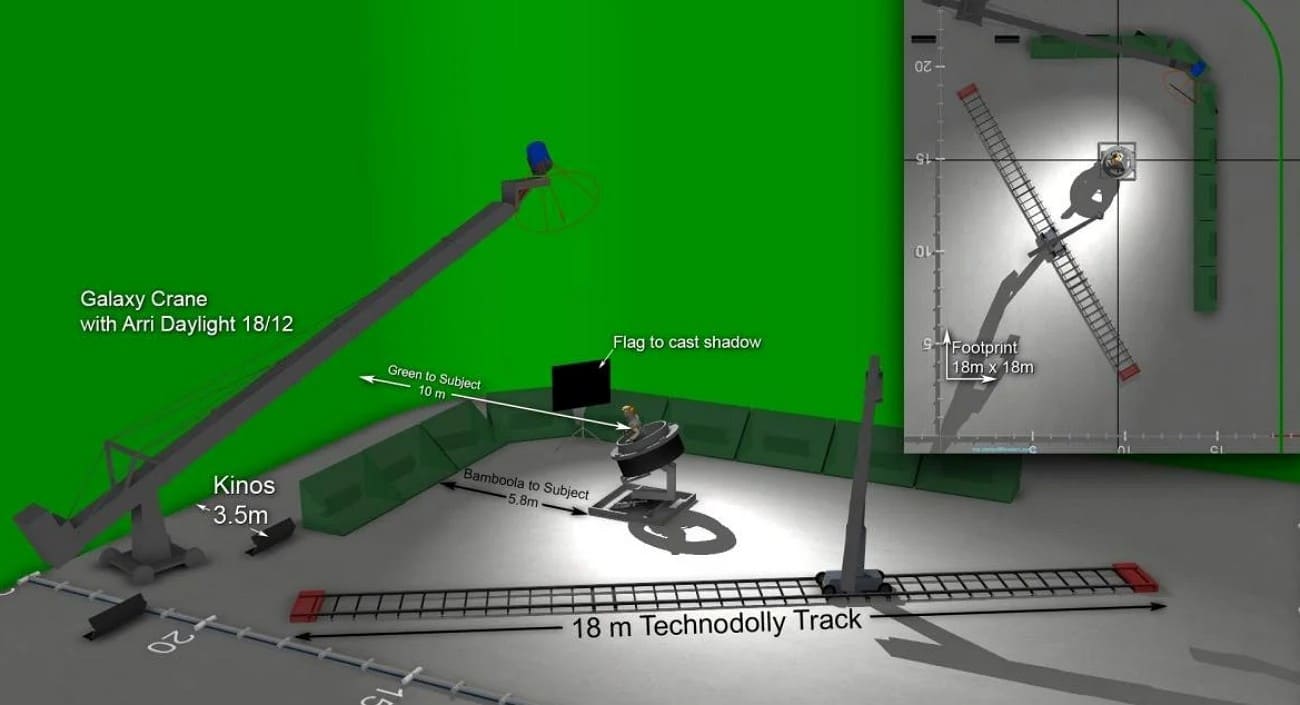
previsualization type 3d previs

5. Techvis

Unlike others, Techvis converts previs into technical data such as camera positions, motion paths, crane heights, and green screen layouts. It ensures planned shots can be executed safely on set and guides equipment setup. Hence, techvis helps the crew avoid costly errors by showing what is possible with the tools and space available.

previsualization type techvis


Part 3. Key Tools & Software for Previsualization

To create effective scenes, it's important to know which previs tools and software are essential for every project. Therefore, this section lists 5 popular softwares with detailed guidance on what makes them best for previsualization: 

1. Autodesk Maya

This previsualization software includes Camera Sequencer tools, enabling previs artists to block out multiple shots. Through this tool, users can even switch angles and cut simple edits directly in 3D without leaving the software. Its animation toolkit, including motion-path and mocap workflow, makes it easy to block character and camera motion. OpenUSD support and a strong plugin ecosystem mean previs scenes and cameras can move smoothly. 

previsualization software maya

2. Storyboarder

Storyboarder is built specifically for fast story exploration, allowing you to sketch boards as simple stick figures. The integrated Shot Generator in this pre-visualization tool lets you create simple 3D scenes with characters, props, and cameras. Essentially, it auto-creates boards from predefined shot types, which is ideal for rapid previs. Besides, you can set panel durations, add dialogue captions, and play back scenes as basic animatics.

previsualization software storyboarder

3. Previs Pro

A program that completely suits previs definition because it allows you to build complete 3D storyboards with characters and props. Its animatics tool adds motion, timing, and pacing; you can turn a static board into a production-ready previs video. Surprisingly, AR virtual cameras and LiDAR imports let you drop virtual characters and sets into real locations. You can also incorporate 3D models, generate props with AI, and export scenes to Unreal.
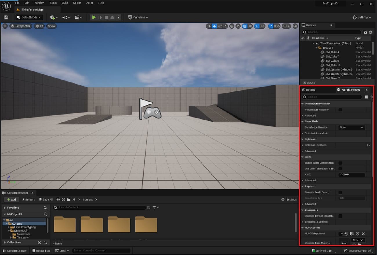
previsualization software previs pro

4. Unreal Engine

Another pre-visualization program whose Cinematic camera actors and virtual camera (VCams) simulate real lenses and sensor sizes. Even its character tool makes it easy to build believable 3D sets where you can experiment with staging. Virtual production workflows and virtual scouting mean previs scenes can flow forward into in-camera VFX. Its Sequencer timeline acts as a built-in non-linear editor, letting you freehand edit.
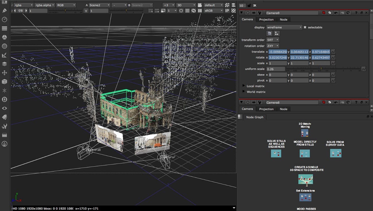
previsualization software unreal engine

5. Nuke

Over 200 compositing nodes make it easy to combine CG previs renders and temp matte painting into editable shot mockups. Nuke Studio/Hiero's multi-shot timelines allow teams to manage entire sequences and temp VFX across many previs shots at once. Customization via Python API enables studios to build previs-specific templates, keeping sequences visually consistent. Moreover, integrated 3D space allows artists to explore staging and lens choices before full 3D composition.  

previsualization software nuke


Part 4. How to Make a Previsualization (Beginner Guide)?

Now that you know the tools, let’s explore how to create a pre-visualization in simple steps mentioned ahead and demonstrated in this video: 

1. Clarify the Idea

The first step is to review your script or outline and determine what parts require previsualization. Subsequently, create a simple shot list covering the description of the camera angle, the way the camera is going to move, and the significant action in a specific shot.

clarify idea for previsualization

2. Choose Previs Format

Next, decide which type of previs is best for your project. If your project is simple, you can use hand-drawn storyboards or photos placed to show the scene. However, if you want to plan timing and camera motion more clearly, create an animatic. Know that an animatic is like a video version of your storyboard, where you arrange each shot with timing and sometimes sound in software like Premiere or After Effects.

choose format of previsualization

3. Build Rough Visuals

Next, draw simple images of how your scenes will appear; they need not be elaborate or flawless. Characters and sets can be depicted using very simple shapes in 2D or 3D. The objective is to concentrate on each shot frame and the movement that the camera is going to follow. 

If your scene includes complex camera movements or special effects, you can use 3D applications to test and refine them easily. This includes Blender, Maya, or Previs Pro to test such movements without much effort.

build rough visuals for previsualization

4. Add Timing and Sound

In making previsualization, have all your shots in sequence and assign each shot an approximate duration. This assists you in the pace, flow, and rhythm of the scene. To test how the sequence will feel, you can also add temporary dialogue, sound effects, or music, even though everything remains rough and not final.

add timing for previsualization

5. Review and Refine

Finally, observe the previs, either alone or with your team, and identify areas for improvement. You may need to adjust shot sizes, camera angles, or timing until the sequence becomes clear and easy to follow. As it feels right, use the finished previs as a guide during production. Thus, it will help you follow the short list, plan your shooting schedule, and better understand the budget.

review created previsualization


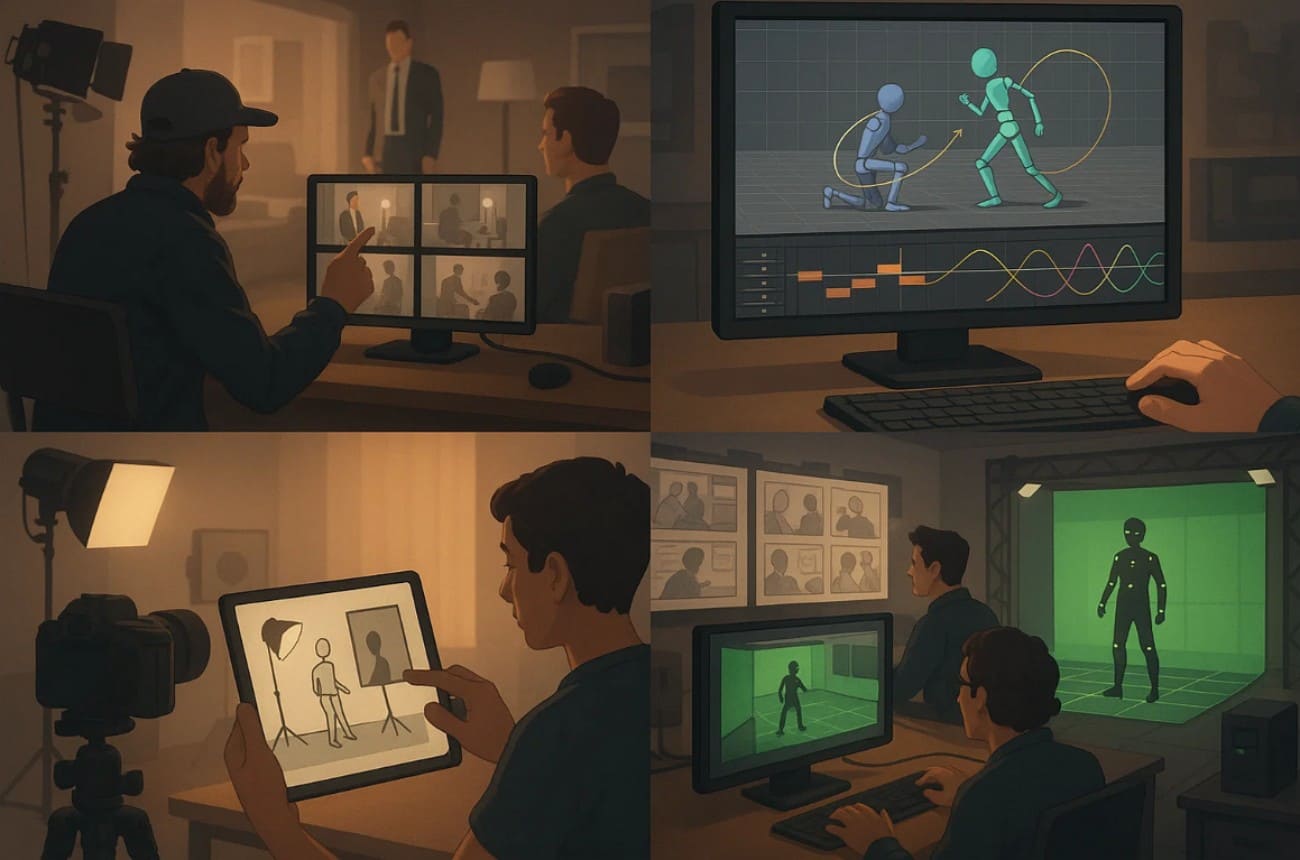
Part 5. Applications of Previsualization

After having the basics of previsualization, here is how you can apply this process in several fields to plan, test, and improve visual projects: 

applications of previsualization

1. Film Production: Previs may be used by directors to design complicated shots, camera movements, and placement of actors. There, the lens choice, framing, and blocking will assist in making scenes clear and efficient prior to shooting.

2. Animation: As an animator, you can rely on previs to set character movements, scene layout, and timing. With rough 3D models and keyframes, you can test flow and pace before the final animation. 

3. Photography: Photographers can also find this solution useful and can plan a lighting setup, angles, and the position of the subjects. Moreover, depth of field, camera positioning, and composition guides warrant the intended visual output.

4. Advertising & Commercials: Ad teams can use previs to design camera paths, story flow, and visual storytelling. Storyboards, effect placeholders, and timing charts will help create precise, appealing commercials.

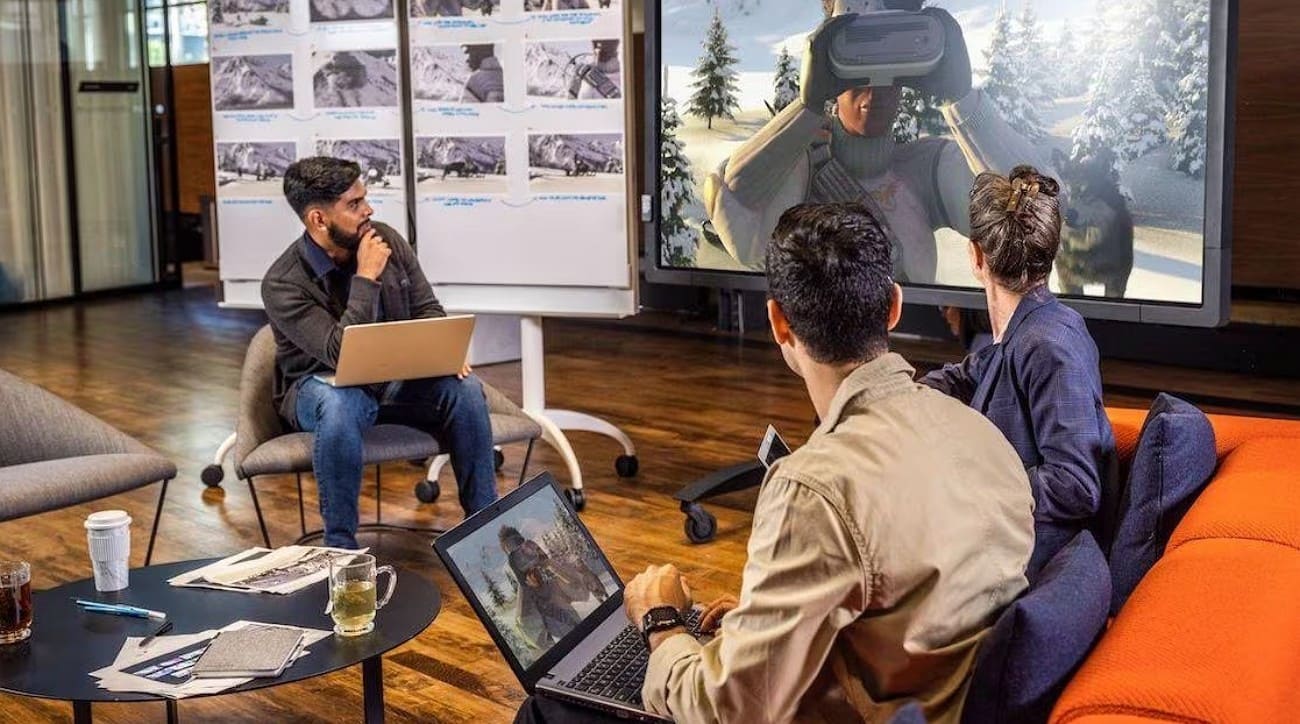
5. Virtual Production & VFX: VFX teams use previs to coordinate stunts, CGI, and virtual set interactions. Thus, camera tracking, green screen layouts, lens simulation, and motion capture ensure accurate results.


Part 6. FAQs about Previsualization

1. What does a previsualization artist do?

A previsualization artist plans scenes and shots to show directors the visual story clearly. They create rough models, storyboards, or animatics so teams can see and adjust each scene.

2. Can I use motion capture technology with previsualization software?

Yes, motion capture data can be added to previsualization software to show character movement accurately. It helps test action, stunts, or complex sequences before full animation or live production begins.

3. What are the best software tools for previsualization in filmmaking?

Popular previsualization software includes FrameForge, ShotPro, Blender, and Maya for 3D and storyboard creation. These tools allow directors to plan shots, camera angles, and sequence scenes before actual filming.


Conclusion

To wrap up, previsualization helps creators plan scenes and test shots before production to save time and reduce errors. This article has explained this process in detail with an extensive guide on how to storyboard, animatics, 3D models, and technical data.

For teams working on more complex previs scenes, a render farm like Fox Renderfarm can be a practical option to handle heavy test renders and previews more efficiently.

Interested

How to Create the Entrance of 'For Honor'
The leading cloud rendering service provider and render farm in the CG industry, Fox Renderfarm, will show you in this post a scene inside "For Honor," the Entrance, created by a student who is learning 3D modeling. The creator completed this work over a period of four weeks by solving problems and challenges with the help of his/her teacher and his/her own efforts. This article is a summary of his/her experience in the creation of this scene.Final result:Analyzing Concept Art &x26; Building Rough ModelsThis is a case of the PBR workflow, specifically utilizing 3ds Max for low-poly modeling, ZBrush for high-poly sculpting, TopoGun for retopology, Substance Painter and Photoshop for texture, and ultimately rendering with Marmoset Toolbag 4.To ensure production progress, in the early stages, the scene was initially constructed in 3ds Max based on the concept art as a large-scale reference for proportions, and then the actual production process began.Rough modelMaking Mid-poly ModelsHouse Structure: serving as the foundation of the scene framework. The house was divided into several parts for construction, including the roof, walls, floor, door frames, steps, and two side stone platforms. Through analyzing the concept art, it was determined that the stone walls and roof tiles employ a repeating texture pattern, which was subsequently applied throughout the scene.The scene props included stone lion statues, lanterns, ropes of hanging tassels, and more. Among them, the stone statues, steps, and several wooden elements were sculpted using ZBrush.The process of creating the mid-poly model involved continuously refining and adding more intricate details based on the rough model. It was important to analyze which models require sculpting and retopology during the initial stages of production, and which models could be reduced in detail to serve as the low-poly model. Conducting this analysis early on significantly improved efficiency in the production process.Mid-poly modelMaking High-poly ModelsThe high-poly modeling stage was relatively intense, involving numerous wooden doors, plaques, walls, as well as stone steps and statues. However, the task became less laborious when it came to identical wooden boards in the scene, as they could be easily adjusted and reused.Statue sculpting:Since the only element in this scene that required complete sculpting was the stone lion, I decided to challenge and improve my sculpting skills by starting from a sphere. After several days of sculpting, I began to see some progress. Then, with guidance from my teacher, I delved deeper into proportions, structure, and finer details.Props sculpting:The wooden boards, during the sculpting process, were meticulously sculpted stroke by stroke to enhance the texture and bring out the grain. Additionally, props like stone steps were also carved.Afterward, the UV unwrapping and baking process followed.Making Low-poly ModelsIn the early stages, we conducted an analysis of the assets. Among them, only the stone lion required retopology, while the remaining props could be obtained through reducing the mesh of mid-poly models.Overall, retopologizing the low-poly model is a relatively simple but patient task. There are several points to consider during the process: 1. Controlling the polygon count of the model. 2. Planning the mesh topology in a logical manner and determining whether certain details need to be retopologized. 3. Evaluating the density of the mesh topology for proper distribution.During the low-poly retopology stage, we encountered few difficulties. We followed a standard of 1m³/512 pixels to create the textures and planned them accordingly based on the predetermined pixel density. Then, we proceeded with UV unwrapping and layout. Throughout this process, we encountered issues such as seams appearing and models turning black. Eventually, we identified the problems as certain areas of the model lacking smooth group separation in the UVs and flipped normals. When placing the UVs, it is important to fully utilize the UV space to avoid wasting resources. Additionally, we needed to redo some of the UV work later on. It should be noted that in 3ds Max, when using automatic smoothing groups, it may not be apparent if the normals are flipped. Therefore, it is advisable to double-check after completing each section.Next was the normal map baking. We matched the high-poly and low-poly models in 3ds Max and ensured that there was some distance between all the models to avoid overlapping during the baking process. If any issues arose with the baked normals, we would repair them in Photoshop. Fortunately, there were no major problems throughout the entire baking process, so minor adjustments in Photoshop were sufficient.Low-poly modelMaking MaterialsI initially conducted material rendering for the sculpture and showed it to my teacher. However, the teacher pointed out some shortcomings. With guidance from the teacher, I gained a new understanding of material rendering. The key is to focus on volume first and then details. Volume here does not solely refer to the presence of volume under lighting conditions, but also the perception of volume even in the absence of lighting, relying only on colors. The addition of darker shades and textures further enhances the sense of volume in the model. Finally, sharpening was performed to make the details more prominent. By following this approach, the materials created would appear three-dimensional under lighting effects.RenderingAfter completing meticulous file organization, I standardized the naming of models, material spheres, and textures. This significantly reduced the workload when using Marmoset Toolbag 4. Once all the preparations were done, I began placing the models, setting up the lighting, adding special effects, and finally positioning the camera for rendering. During this process, a considerable amount of time was spent on lighting. The coordination between model materials and lighting never seemed to achieve the desired effect. However, with guidance from my teacher, I was able to improve the overall result.The above is our experience sharing the production process of the Entrance for the game "For Honor".Source: Thepoly
More
2023-09-28
Learn How to Make a Handheld Fan in 3D
Today, Fox Renderfarm, the industry's leading cloud rendering service provider and render farm, will bring you a 3D tutorial that explains how to make a handheld fan. Let's get started right now.First import the image, use the straight line tool to draw the length of the handle, then use the rotational molding tool to create the handle and add a cover.Generate a rectangle using the center point, adjust it to the appropriate size, and then generate a circular runway. At this point, use the fitting tool to get the appropriate shape.Select the circular runway that was just generated, hold down Shift to extrude the faces on both sides and add a cover, then use the shell tool to shell both sides.Copy the inner edge line of the shell, extrude the face and add the cover, pull off the inner face to keep only the outer side, and then chamfer to generate the outer layer of the shell that needs to be hollowed out.Use curves to draw the edge shape of the connecting axis, then use rotational molding to generate the surface, and then add the cover to generate the solid.Connect the rectangle diagonal, use the diagonal to generate a round tube, and adjust the angle and thickness of the tube so that the angle and thickness of the tube match the reference picture.Draw a diagonal line again and use the Line Array tool to array along this line, where the number of arrays is 18.Use the object intersection line function to select the round tube and the shell to be hollowed out, determine whether the position matches by the object intersection line, adjust the position and then cut to get the hollowed out object.Use the Rectangle tool to generate a runway circle, adjust it to the right size, then cut and combine it with the hollow object and offset it inward to get the solid. The same can be done for the outer runway circle, here you need to make a copy of the hollow object for backup.Use the mirror tool to mirror the hollowed-out model made in the previous step to the back, then use the method in the fourth step to get an unhollowed-out shell, generate a rounded rectangle and cut it according to the second reference picture, then use the combination tool to combine, and finally offset the surface to get the solid.Use a rectangle to frame the size of the button, then use a straight line to connect the midpoint of the rectangle, next use the center point tool to generate a circle, and squeeze the circle to the right size and adjust the height of the button.Split the button and the handle for spare, and then chamfer the top of the handle for the next step.For the base, again using the rotational molding tool. First draw the edge shape using curves, then rotate the shape and cap it to create a solid.Now perform the Boolean split between the handle and the base, then detach the surface. Next, copy the edge line, move the inner circle downwards, use the double rail sweep to generate the surface and combine it to obtain the base shape.Use the center point circle and rectangle tools to generate the button and indicator light shapes on the handle, extrude the solid and then perform a boolean split with the handle to get the handle shape and the indicator light.Use the Rectangle to create the runway circle and rotate it 45° to get the "x" below, then use the Trim tool to trim off the excess lines and combine them. After extruding the surface, use the Boolean split tool to split it to get the "x" icon.Now create the circular texture on the button. First abstract the structure line to get a button-sized circle, then generate a circle solid at the circle node, and use the Array Along Curve tool to make an array. Arrange the five columns in sequence according to the image and mirror them to get the desired texture. Finally, we use Boolean split to get the button shape.Chamfer the intersection of the button and the handle, and chamfer the intersection of the handle and the base.Use the curve to draw the fan shape, then use the XN tool to generate the surface, and array along the center point. The number of arrays here is 5. Adjust the fan blade position and extrude the fan blade solid.Check the model and chamfer it to complete the model.The next step is to render the product. First, divide the product into four layers, one for the orange object, one for the flesh-colored object, one for the metal connection, and one for the self-illumination. Then start rendering.First adjust the model position by aligning the model to the ground in the Advanced Options.Set the model materials to the model in turn. Note that you need to turn down the metallic shine of the metal joints in order to get a frosted look.Adjust the self-luminous material on the handle to the right intensity in accordance with the light, and choose white as the color.Set the setting options in the image to Press Exposure, High Contrast, and Photography.Change the background color in the environment settings. Use the straw tool to absorb the image color, turn down the brightness of one light in the HDR editor, hit the light on the hollow surface, adjust the shape of the light to rectangle, and then hit a main light on the left side of the product to make a shadow appear on the right side.Adjust the object position in the camera, lock the camera, and finish the rendering.Source: YBW
More
2023-07-20
How to Use VFace and Make Effects in Arnold?
In this article, Fox Renderfarm, the CG industry's leading cloud rendering service provider and render farm, will share with you how to use VFace and how to restore effects in the Arnold renderer. The author is CaoJiajun.Firstly I purchased some VFace materials from the official website to get the following files.We will mainly use the above files for this sharing, they are our main materials to make high quality details of the face. VFace provides 2 types of facial models, one for the head with open eyes and one for the head with closed eyes, choose one of them according to your needs. If you are doing a model that needs to be animated with expressions in post, I would recommend choosing the model with closed eyes, as the open eyes model will cause the eyelids to stretch when you do the blink animation. You don't need to worry about this for still-frame work.Let's start with the production process. It's actually very simple, wrap your own model with a VFace model through Wrap or Zwrap, then pass the map and finally render it in Maya or other 3D software. The process is simple but there will be a lot of things that need to be taken care of in there otherwise the facial details will not be rendered correctly.1 Model CleaningFirst we need to load the model provided by VFace into ZBrush and match it to our sculpted model.Then you can head into Zwrap or Wrap for wrapping.Lastly, the wrapped model is imported into ZBrush to replace the VFace model.In ZBrush we use the Project brush to match the face of the wrapped model more precisely to our own sculpted model, once matched you will have a model that matches your sculpted model perfectly, at this point we can go into Mari for the map transfer.2 Using Mari to Transfer the MapIn Mari we first set up the project, import our own sculpted model or the wrapped and matched XYZ model, then remove the other channels in the Channels and keep only the Basecolor channel, and we can customize the channels as we wish.What we see now is how the model looks when imported into Mari. At this point we need to set the custom channels DIFF\DISP\UNITY\ to import the VFace map.Firstly, the DIFF channel is set at the original size of 16k and the Depth is set at 16bit (later on there can be more color depth control and of course it can be set to 8bit). The key point is that when the color depth is set to 16bit or 32bit, the color space needs to be set to linear and 8bit to srgb.Keep the size of displacement map at 16k. I recommend setting the Depth to 32bit, as you will get more detail of displacement, and keep the color space linear, with Scalar Data ticked (as the displacement map is a color map with 3 channels of RGB, you need to keep the greyscale data).The blend map settings are the same as the color map, but Scalar Data also needs to be ticked (this map is used as a color mask for toning or as a weighting mask).Next we can use the object panel to append our own model in preparation for the transfer of the map.Right-click on any channel and select the Transfer command in the pop-up menu to bring up the menu for transferring the map.In the transfer menu select the channel which needs to be transferred in the first step, set the transfer object in the second step, click on the arrow in the third step, set the size in the fourth step and finally click on the ok button.I generally recommend passing one channel at a time as it is very slow and takes a long time to wait. For size I usually choose 4k for color, 8k for displacement and 4k for mixing channels. This step requires a lot of patience!VFace original effectThe effect after transferAfter the transfer we can export the map. The export map settings are shown in the figure. We need to pay attention to the color space setting (in the red box). The color space of the color channel is set to linear and should also be set to linear when exporting. The export of displacement and hybrid maps is a bit more unusual, as we set the color space to linear when creating the channel, but the export needs to be set to srgb, as both the displacement and hybrid maps are a combination of the 3 channels R,G,B to form a color map. Finally click the export button and it's done.VFace original color effectColor effects after exportingVFace original displacementEffect after exportIn short, your output map needs to be the same color as the map provided by VFace, either too bright or too dark is an error.3 Arnold RenderingDefault settingsAt this point we can go to Maya and render the VFace map we have created (we won't go into the lighting environment and materials here, we will focus on the link to the replacement map). First we import the passed VFace map and render it by default to see what we get. Obviously we get an ugly result, so how to set it to get it right?Here we add an aisubtract node (which you can interpret as a subtraction or exclusion node), because the default median value of VFace is 0.5 and arnold prefers a replacement map with a median value of 0. So we enter the VFace color into input1 and change the color of input2 to a luminance value of 0.5. This is equivalent to subtracting the 0.5 luminance info from the default 0.5 median luminance of VFace, and we get a displacement with a median value of 0.Median value 0.5Median value 0After setting the median we can add an aimultply node. This node can be interpreted as a multiplyDivide node, which has the same function as Maya's own multiplyDivide node and controls the overall strength of the VFace displacement. We can output the color of the aisubract node to the input1 node of aimultply and adjust the overall strength of the detail displacement of VFace by using the black, grey and white of input2 (any value multiplied by 1 equals 1, any value multiplied by 0 equals 0, all the colors we can see in the computer are actually numbers to the computer. We can change the value and thus the strength of the map by simple mathematical calculations, once we know this we can see why we use the multiplyDivide node to control the strength of the displacement).Next we add an ailayerRgba node. The R, G and B channels of the aimultipy are connected to the R channels of input1, 2 and 3 of ailayerRgba, and through the mix attribute of this node we can control the intensity of the displacement of each of the three VFace channels (R, G and B), and after a series of settings we can get a correct and controlled rendering of the VFace displacement.VFace-dispZBrush-dispVFace+ZBrush dispZBrush Export Displacement SettingsAlthough we have a correct and controlled VFace displacement result, it does not combine with the displacement we sculpted in Zbrush and we need to find a way to combine the two to get our final displacement effect.Here I used the aiAdd node to add the two displacement maps together to get our VFace displacement + ZBrush displacement effect (of course you can also use Maya's plusMinus node).It doesn't matter how many displacement map elements you have (such as the scar on the face, etc.), you can structure them through the aiAdd node to get a composite displacement effect. The advantage of making it this way is that you can adjust the strength and weakness of each displacement channel at any time, without having to import and export them in different software. It is a very standard linear process approach.Default effectAfter color correctionFinally we apply the passed color to the subsurface color, and by default we get a very dark color mapping, which is not wrong. The VFace default model will be the same color. We can correct the skin color by using the hue, saturation and lightness of the colourCorrect node. This is why I choose 16bit colors to bake with, so I can get more control over the colors and get a correct result after color correction (of course the current result is just a rough mapping, we can still do deeper work on the map to get a better result).As a powerful render farm offering arnold cloud rendering services, Fox Renderfarm hopes this article can give you some help.Source: Thepoly
More
2023-07-19
Business Consulting

Global Agent Contact: Evan Zhang

Email: evan.zhang@foxrenderfarm.com

Marketing Contact: Evan Liu

Email: evanliu@foxrenderfarm.com

Message Us:
Newsletter
Keep up with our latest software updates, special offers and events!
Copyright © 2025 FoxRenderfarm.com. All Rights Reserved.