Maya Tutorial丨Practical UV Techniques

Maya Tutorial丨Practical UV Techniques

In this article, we join forces with Fox Renderfarm, the top cloud rendering service provider and render farm in the industry, to bring you an in-depth exploration of Maya's powerful UV unwrapping and UV layout planning features. Prepare to unlock new realms of efficiency as we unveil techniques that will streamline your 3D modeling workflow, empowering you to harness the full potential of UV mapping in your creative endeavors.

1. UV Editor

The UV Editor can be used to view UV maps of polygons, NURBS, and subdivision surfaces in a 2D view, allowing for interactive editing. You can open it from the Modeling menu window > UV > UV Editor.

UV Editor 1

UV Editor 2

In the UV Editor, you can access all the major UV functions through the editor's menu, toolbar, or UV toolkit. This time, it's not just about introducing UV editor commands but also sharing some more commonly used practical commands and methods based on experience.

2. UV Toolbar

Including the UV Editor and viewport.

UV Toolbar

Shell borders

In the toolbar, the command on the left is 'Texture borders,' which we often use to check if the borders are aligned properly on the model. 'Shell borders' is similar but emphasizes the display with colors. Sometimes, using just 'Texture borders' can be challenging to quickly visualize the correct positions, especially when UVs are densely packed within a tile.

Shell borders

Display Images

After enabling 'Display Images,' if you want to view the different textures assigned to this material, you can click on the adjacent dropdown arrow. A dropdown menu will appear where you can switch between whether you want to see the normal map displayed on the UVs or the base color map (as shown in the figure). Any other added textures can also be displayed.

Display Images 1

Display Images 2

UV Toolkit

By default, the UV Toolkit is displayed on the right side of the UV Editor.

Drag

In the UV Toolkit, when you switch to the 'UV Shell' display mode, the default selection method is 'Pick/Marquee,' which allows you to select by clicking or dragging a marquee selection box. When you switch to 'Drag,' you can select by holding down the left mouse button and dragging the mouse cursor.

Drag

Topology

In the UV Toolkit, clicking on 'Topology' from the 'Symmetry' dropdown menu allows you to select one side of the UV while simultaneously selecting the other side. This feature is very useful when organizing or correcting UVs for biological models. This functionality is synchronized with the Symmetry feature in the Modeling Toolkit.

Topology 1

(The two blue symmetrical lines are shown in the following image)

Topology 2

Selection Constraint

The options in the dropdown menu include:

Back-facing/Front-facing, Geometry Borders, Texture Borders, UV Edge Loop, UV Edge Ring, and UV Shell. These limited selections will be very helpful when unwrapping and organizing UVs, eliminating the need to manually select each edge or ring.

Selection Constraint

When the 'Shaded' display mode is activated, red represents the back-facing, and blue represents the front-facing. When 'Back_Facing' is activated, only the red parts can be selected, and when 'Front_Facing' is activated, only the blue parts can be selected.

Back_Facing

Geometry Borders (Only the edges of the model itself can be selected)

Geometry Borders

Texture Borders refer to the borders of the texture, which are all manually cut edges, i.e., edges used as UV seams.

Texture Borders

UV Edge Loop is a continuous loop edge.

UV Edge Loop

UV Edge Ring is a ring-shaped loop edge.

UV Edge Ring

UV shell refers to each individual UV split.

UV shell

Select By Type

Back-facing, Front-Facing, Overlapping, Non-Overlapping, Texture Borders, Unmapped. Among these, the ones commonly used are Overlapping, Back-Facing, and Unmapped. These are typically used to check for overlapping UVs, backfaces, and models that were forgotten to be unwrapped.

Select By Type

Transform

When you want to move UVs from one quadrant to another, you typically set the Move value to 1. Alternatively, you can set it to 0.1 (a decimal value) to move by one small grid. You can click on the arrows (up, down, left, right) to move, or hold the Alt key while pressing the arrow keys on the keyboard. Once you've planned how to categorize materials for each quadrant or row of quadrants, you can use this command to move them to the respective categories in other quadrants.

Transform

Texel Density

This tool is very useful and practical. When you want to ensure that every UV split has the same texture display size, you can select a primary UV, click "Get" to obtain the current texel density (a numerical value), and then single-select or multi-select other UVs and click "Set". This will apply the texel density value to the other UV shells. As a result, all UV shells will have a consistent texture grid size display. The texel density value is determined based on the "Map Size" below, such as preset values like 512, 1024, 2048, and so on.

Texel Density

Tile Labels

Activating "Tile Labels" will display the specific numbers of each tile, making it convenient to manage UDIMs.

Tile Labels

Straighten UVs

Under the "Unfold" command menu, it's advisable to use "Straighten UVs" for some tubular models. This straightens the UVs, making it easier to add textures during the texture painting stage. If the UVs have curvature, adding straight textures can be cumbersome.

Straighten UVs

Distribute

When dealing with models with completely repeated arrangements, under "Arrange and Layout," you can use "Distribute." Click on the symbols for up, down, left, or right, and set a value (based on the UV grid distance) to quickly and neatly arrange the selected model's UVs.

Distribute

Stack Shells

Sometimes you only need to apply one texture to repeated models. You can achieve this by using "Stack Shells," which overlap all identical UV shells together.

Stack Shells

UDIM

When using UDIMs, if you have the same model, such as identical pieces of wood (or left and right hands), you can arrange them as shown in the image below. This ensures that the UVs in both quadrants are in the same position and size. This way, when painting textures in Mari, you can directly copy and paste.

UDIM

Above is the sharing of some practical and useful UV techniques. If you want to speed up rendering, why not use Fox Renderfarm's cloud rendering service for acceleration? Currently, Fox Renderfarm also offers a $25 free trial coupon.

Source: Thepoly

Welcome to join us

render farm free trialRecharge $100 & Get Extra $200 Render Coupon!

Recommended reading


Top 9 Best And Free Blender Render Farms of 2024

2024-08-30


Revealing the Techniques Behind the Production of Jibaro "Love, Death & Robots", Which Took Two Years to Draw the Storyboard

2024-08-30


Top 10 Free And Best Cloud Rendering Services in 2024

2024-08-08


Top 8 After Effects Render Farm Recommended of 2023

2024-08-30


Shocked! The Secret Behind Using 3D to Make 2D Animation was Revealed!

2022-05-11


How to Render High-quality Images in Blender

2024-08-30


Easy Cel Shading Tutorial for Cartoon in Blender Within 2 Minutes

2022-07-01


8 Best And Free Blender Cloud Rendering Services in 2024

2024-08-30


Partners

Interested

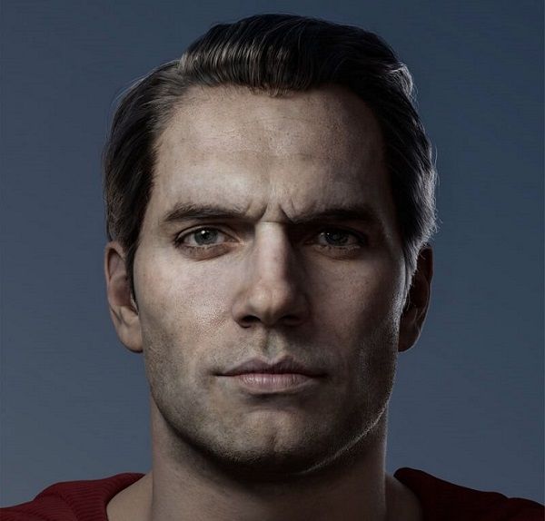
Learn How to Make a Henry Cavill Superman in 3D
If you're a 3D learner and love the Superman movie, it's time to make a 3D Superman just for you. Now, follow the industry's best cloud rendering service provider and render farm, Fox Renderfarm, to see how CG artist H cheng made his Superman.Final results of 3D Henry Cavill Superman:The tools used in making 3D Henry Cavill superman are as follows:High-poly: ZBrush, Marvelous DesignerTopology: Wrap4D, MayaMapping: Mari, Substance PainterHair: XGenRendering: Arnold/UECollection of MaterialsBefore we start, we need to decide the theme and collect the required reference material. I chose Henry Cavill as Superman model for this project. Then we can try to collect as many photos of his stylized look shown in the movie as reference.Next, in the portrait making process, we can find some multi-angle life photos or portraits of Henry Cavill, which is convenient for us to observe the structure and capture the shape.Model SculptingIn the modeling process, we need to set the size and proportion of the realistic character model at the beginning. Having a realistic scale for reference will help us in the subsequent detailed production, as well as hair and material production.When working on realistic character or orc-like projects, solid anatomical knowledge and sculpting skills are essential. These factors fundamentally determine the depth and quality of our models. Therefore, it is necessary to practice sketching regularly. For example, I also do similar sketching exercises in my daily routine, trying to control each sketch exercise within half an hour with a specific purpose. During the practice, I can use the built-in slice tool in ZBrush as a basic framework. Its size is based on realistic human head proportions, which allows us to practice skull or muscle anatomy. The exercise is shown in the image below:Once we have acquired a certain level of foundational skills and a wealth of theoretical knowledge, we can use our understanding of anatomy to engage in sculpting exercises for designing orc-like characters.With a solid foundation and extensive knowledge of anatomy, when working on character designs like this, we can analyze the anatomical structures of the human, animal, or orc-like creature in a rational manner during sculpting. Mastering the anatomy of the head, body, or other forms allows us to analyze and refine the design in a logical way. For example, in the case of this orc head model, as shown in the image below:There is actually no difference in terms of muscle structure between his face and a realistic human. We analyze it rationally because it has a different skeletal structure from a human's, and its facial features have distinct shapes, resulting in noticeable differences in the muscle structure. However, under the overall skeletal framework, their muscle anatomy is the same. It's like the same piece of clothing hanging on different hangers, forming different folds, but fundamentally, its essence remains unchanged. Therefore, the formation of the fold shapes follows certain patterns that can be observed. This requires us to have a solid theoretical foundation to support our analysis.We achieve large-scale detailed sculpting using ZBrush, making effective use of scan-based mesh retopology techniques. For quick mesh symmetry, we directly utilize R3DS Wrap. R3DS Wrap is a professional-grade 3D topology tool software that has revolutionized the way we handle 3D scan data. When working with human scans or similar subjects, existing basemeshes can be loosely matched to each scan. It also provides a set of highly useful scan processing tools such as decimation, mesh filtering, and texture projection. Thanks to its node graph architecture, once a single scan is processed, the same approach can be applied to an unlimited number of other scans.Mapping of CharacterAfter completing the high-resolution sculpting of the body, we use Mari to start creating the skin texture channels. The overall workflow is quite simple, and I'll briefly describe it.For color painting, we utilize XYZ scan materials and wrap them using the ZWrap plugin, which serves as a realistic texture base. Then, in Mari, we make adjustments and add details to the projected textures. We overlay multiple color biases on the color map to achieve a rich color effect. Since gorillas have black skin, the details we paint or obtain from XYZ materials may not be clearly visible. Therefore, we add a layer of lighter color contrast to enhance some details.When creating roughness and specular maps, we need to pay attention to the variations in highlight levels and roughness intensity. The highlight map can be created by inverting the colors of the roughness map and then making adjustments accordingly. For the complete set of skin texture maps, I have created the color, specular, roughness, and SSS (Subsurface Scattering) strength and color maps.Production of ClothingFor clothing production, I primarily rely on Marvelous Designer for fabric simulation and utilize ZBrush for quick sculpting and refinement.Marvelous Designer has become widely used in CG art production. Therefore, it is essential for us to learn and master the basic usage of this software.I am not particularly skilled in using Marvelous Designer myself. I am only familiar with its main function of fabric simulation, which assists in model creation. To create realistic clothing patterns, it is necessary to have a basic understanding of garment cutting theory, especially for formal or workwear attire. Details such as waist openings or cuff offsets can affect the final result of fabric simulation. For unique designs, we can refer to existing paper patterns as references.Of course, when working on the Superman costume, I didn't follow such strict procedures. Since it is a form-fitting suit, I directly created the base mesh in ZBrush and imported it into Marvelous Designer for fabric simulation and folding. Marvelous Designer can quickly assist us in achieving small wrinkle formations around muscle compressions and structural transitions. It is very convenient to use in this regard.The process of creating textures for clothing is relatively simple. I directly imported the model into Substance Painter and used a tiled texture as the fabric pattern for the garment. Then, I assigned a base color and added some procedural textures as needed. To achieve the desired fabric texture effect, I adjusted the material nodes in Maya, which provides similar results.Production of MaterialsCreating materials for skin is very straightforward. The surface material effect in Arnold can directly present a very natural and realistic result. When adjusting the skin material nodes, it is important to note that the value of surface scale is influenced by the scene's scale, and it should complement the color of the radio to achieve the desired effect. When tweaking the parameters, it is helpful to enable real-time rendering to observe the effects while making adjustments.Production of HairWe use XGen for hair styling as it is a widely-used and highly effective tool for creating hair in the industry.Traditional XGen provides high control and flexibility over the styling of hairs, allowing us to meet most of our requirements. When working on the guide hairs, we need to pay attention to the hierarchy and even distribution of the guides. We can also utilize masking painting and the addition of modifier nodes to achieve different hair descriptions and styles.Above is the main process of making the 3D version of Henry Cavill Superman. The next steps are material rendering and connecting each part, which will not be explained in this article. We hope this article is helpful to you.Source: H cheng
More
2023-07-13
How To Rebuild Avatar With Arnold For Maya
In 2009, a sci-fi film Avatar swept the world. This film won a lot of honors, but as a CG enthusiast, the greater fun is still exploring the production process of this film. In Avatar, many characters and scenes are made using Maya. As the leading cloud rendering services provider and render farm, Fox Renderfarm will introduce the Avatar as a case by Arnold and Maya to introduce the software.Part 1. Collection of materialsMaterial collection is an important step, and the more time you spend collecting material, the less late errors will be. When making the Avatar model, I used the web to collect a lot of real material and video reference. You can add some of your own understanding during the production process. You can also try different brush strokes when post-production in ZBrush, and finally unify the whole character. Here are some of the materials I collected. Part 2. Maya basic modelUse Maya's own box as the basic model, first adjust the general proportion, and then start from the large-sized model parts, so that you can grasp the overall feeling of the character in a relatively short time, and easily modify the scale. As far as possible, the wiring should be as clean as possible. It is not necessary to describe too much detail. In particular, pay attention to the structural turning of the head to facilitate engraving later.Step 1: This role, gives me the feeling is a combination of feline and human face, the upper part of the face is a lion, the lower part is a human. I decided to put more effort into her lower half of the face and tried to understand the upper half of the cat's face. After analyzing these things, we can grab some of her characteristics to start modeling.I made a simple model, this time there are very few lines, it is very convenient for you to adjust the feeling. At this time, the proportion and position of the character's lower jaw and facial features were fixed. Step 2: Add one line while adjusting and perform local detail processing.Eye, eyebrow and cheekbones, here are the low mold and final wiring diagram. Part 3. Adding ZBrush DetailsAccording to the previous reference to determine some of the details of the role structure, subdivision in ZBrush, improve the number of faces of the model to add some details to the model. For example, pores, texture of the lips, etc.Step 1: First perform Maya's cleanup to check if there are more than four sides. Export the obj model without problems. Step 2: Import ZBrush to add details. Use a few skin brushes. Detail breakdown and detail addition. Part 4. Mapping the TextureBecause there is already a film and television as a reference, the texture is closer to the content of the film. Here are some of the material I collected.You need to make sure the uv is correct before drawing the texture. I am using the UVLayout plugin to split the model UV. Pay attention to the position of the tangent at the time of splitting, try to put it in the place where it can't be seen, so as to avoid the seam problem. The mapping of the texture here is made by combining Mari and ps. In order to quickly grasp the process of drawing textures using mudbox here. These are the uv splits using plugins. It's worth noting that sometimes splitting out is not ideal and needs to be re-edited in the Mayauv editor.The overlapping parts in the red part of the figure can be adjusted in the uv editor. The final result is as follows. After the UV editing is done, it is necessary to draw the texture and draw it here using the mudbox.Firstly, subdivide the model and then export obj. The second is to open the mudbox and import the model. Select a brush. The shader looks at your personal habits and can switch between viewing highlights and non-highlights. Select the brush and click New Layer on the model to select the map size and format as needed.I am here to choose 4096*4096 size for clarity. And named as the background color, in order to put the background color on the model, to prevent the back when painting the map. The new layer adds the pattern, which can be adjusted in conjunction with the layer blending mode. To achieve the right results. Generate textures and export them after making multiple adjustments. And add textures in ps. And the root layer is created to generate the corresponding 3s highlights and bumps.Part 5. RenderingLight setting: The first step, we basically use the most basic three-point lighting principle to first adjust the intensity of light to achieve the required intensity. Note that this is the arnold renderer that is utilized, so the default light is attenuated with light. The lighting test of the advanced model (the model without the map) pays attention to the contrast of the cool and warm of the light.The three-point lighting is generally the primary light source auxiliary light and contour light, pay attention to the contrast between the main light source and the contour light. There is also an application with skydemo light to simulate the surrounding environment.Setting of the shader ball: In order to better express its texture and skin characteristics, we will use the corresponding skin material.The first step: Since the texture has been drawn before, the respective skin layers whose inherent color is blue are also adjusted according to the inherent color. Connect all the textures to the corresponding properties of the shader and adjust the parameters.Here, five textures are connected to the skin's three-layer highlight and normal map. Then adjust and test the lights.Render channel output: Render the corresponding channel, which is more convenient to adjust later.They are id, normal, highlight, ao, sss, etc.Channel synthesis: The rendered layer is synthesized in ps, the ao channel is synthesized by the method of the film stacking, and the highlight channel is synthesized by the screen method. The normal channel can be synthesized in nuke to re-adjust the light. It is possible to directly adjust the eyelashes and adjust the background lighting effects and color in the ps.Adjust the desired effect with the final adjustment. That's all there is to explain about the making of Avatar, we hope you've been inspired. If you are looking for a render farm, why not try the fast and TPN-accredited render farm, Fox Renderfarm, who offers a $25 trial.
More
2023-04-25
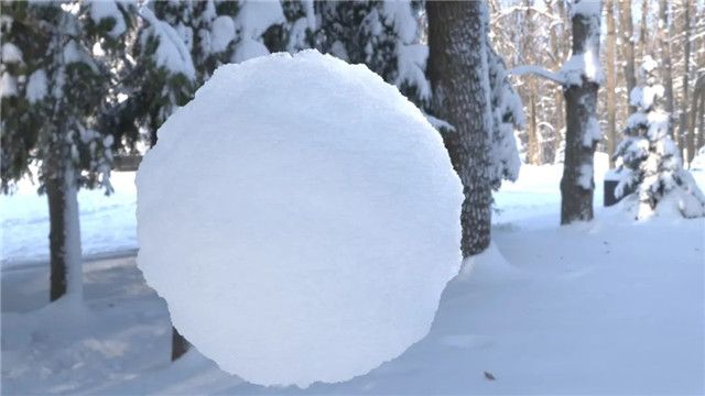
How to Create Snow Material in Maya?
In this article, Fox Renderfarm, the industry's leading cloud rendering service provider and render farm, will bring you a Maya tutorial about how to create snow material in Maya.Step 1. Create an aistandsurface material.Step 2. Add two parallel lights and render.Step 3. Connect a displacementShader.Step 4. Connect a Fractal node to the displacementShader and give Displacement a value (here 0.2).Step 5. Find subdivision, and change Type to catclark. Set Iterations a bit larger (4 here).Step 6. Adjust the Amplitude, Ratio and Frequency Ratio parameters on the Fractal property appropriately to match the effect of Displacement.In the first layer of Fractal, we mainly handle the large undulating silhouette of the snowball.Step 7. Add aiMixShader, and also raise Roughness.Step 8. Connect the first layer Fractal node to the input interface Shader1 on the aiMixShader and change the blend mode to Add.Step 9. Create a second Fractal node to connect to the aiMixShader input interface Shader2 and adjust the parameters. Create details of the grain undulations on the snow surface through the second Fractal layer.Step 10. Go back to the aiStandardSurface material sphere, adjust the IOR to 1.330 and turn on Substance.Step 11. Add HDR and render for testing.Step 12. On the surface of the snow there should also be some tiny dots of high-gloss crystals, which can be created using Coat.Step 13. Adjust the angle of the parallel light and set the Intensity to 6. Gives highlights to the edges of the sphere. Make the whole sphere more three-dimensional (highlights, shadows and reflections) and translucent (subsurface scattering).Step 14. Improve the render quality and make the final render.Author: Ji Wei
More
2023-04-06
Business Consulting

Global Agent Contact:Gordon Shaw

Email: gordon@foxrenderfarm.com

Marketing Contact: Rachel Chen

Email: rachel@foxrenderfarm.com

Message Us:
Newsletter
Keep up with our latest software updates, special offers and events!
Copyright © 2024 FoxRenderfarm.com. All Rights Reserved.