

Top 9 meilleures fermes de rendu Blender gratuites
2026-03-26


What Is Texture Mapping? A Simple Texture Mapping Guide
3D Tutorial
Texture mapping adds detailed images to 3D models. Learn how texture mapping works, key types, benefits, and where texture mapping is used in modern graphics.

Learn Parallax Mapping: Add Depth and Realism to Your 3D Scenes
3D Tutorial
Parallax mapping adds realistic depth to flat textures in 3D scenes. Learn how it works, improves graphics, and enhances games and visual projects.

Path Tracing Explained: How It Works, Software Support, and Best Practices
3D Tutorial
Learn what path tracing is, how it works, which software supports it, and how it differs from ray tracing. Understand noise, performance limits, and best use cases.

What is Screen Space Ambient Occlusion (SSAO)?
3D Tutorial
Learn what Screen Space Ambient Occlusion (SSAO) is and how it improves 3D graphics with depth, shadows, and realistic ambient occlusion effects.
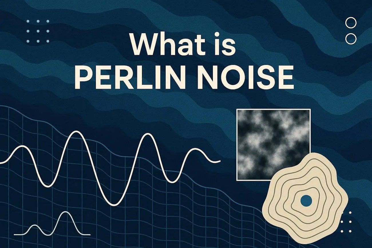
What Is Perlin Noise? Definition, Principles, and Workflow
3D Tutorial
Learn what Perlin Noise is, how it works, its core principles, step-by-step workflow, and real-world uses in games, film, and procedural graphics.
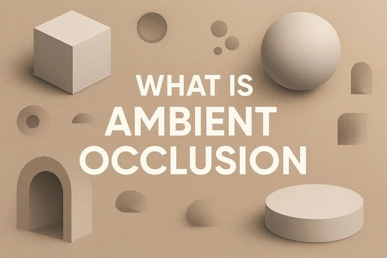
Ambient Occlusion: What It Is, How It Works, and When to Use It
3D Tutorial
Learn what Ambient Occlusion is, how it adds depth to 3D scenes, and when to enable it. Improve realism in games, VR, archviz, and animations.
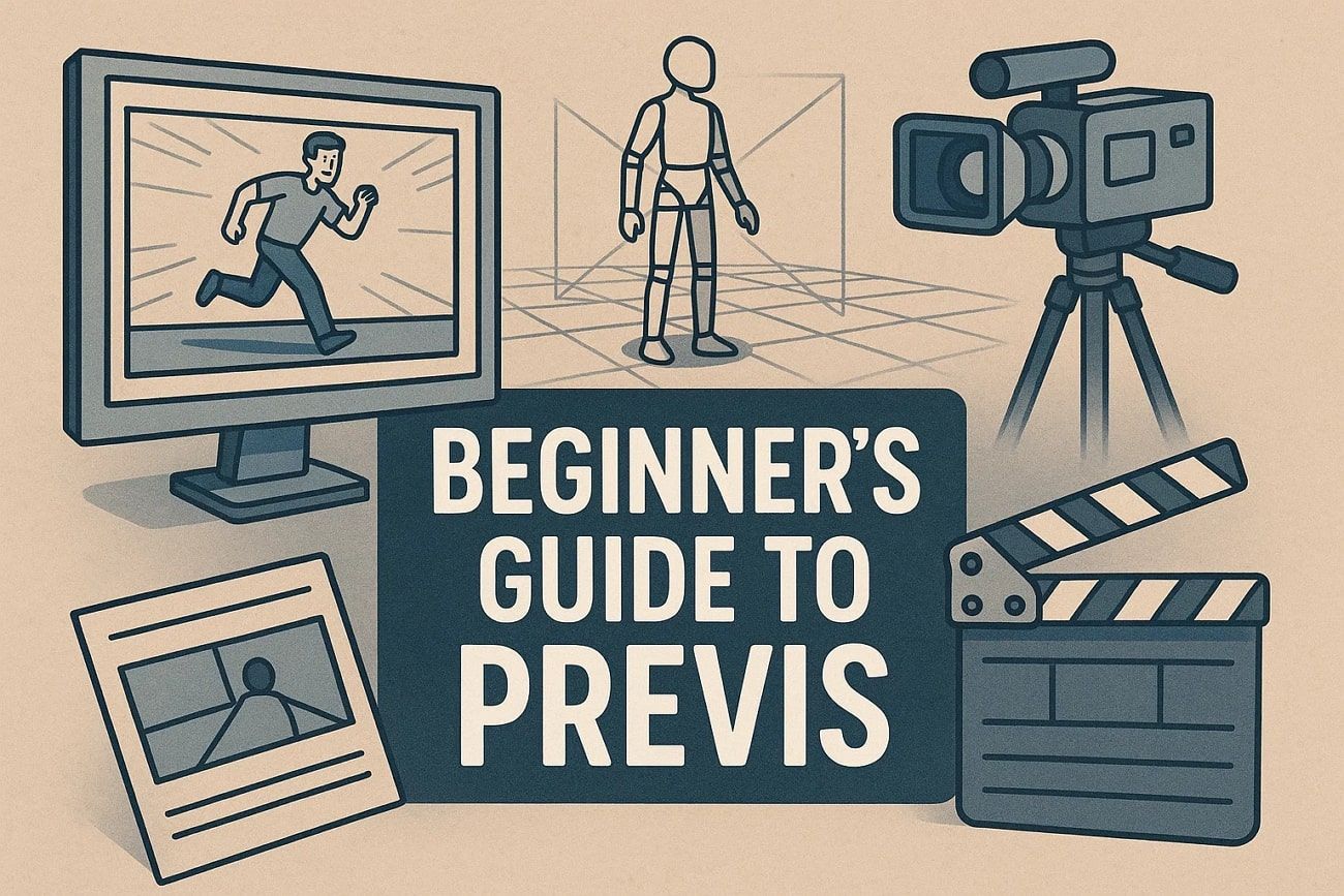
A Beginner’s Guide to Previsualization for Film and Animation
3D Tutorial
Learn how previsualization helps plan film and animation scenes, improve shot clarity, save time, and guide creators from storyboards to 3D models efficiently.
What Is Caustic in Optics? A Clear Explanation with Render Tutorial
3D Tutorial
Find out what is caustic, and how light creates concentrated bright areas. This guide explains the formation and simulation of focused light patterns clearly.
How to Add Motion Blur in After Effects for Smooth Animations
3D Tutorial
Learn how to enhance your videos with motion blur in After Effects. This guide explains settings and common issues to help your animations look realistic.

Step-by-Step Guide for Smooth Blender Camera Movement
3D Rendering
Wonder how to move camera in Blender? This guide helps you create smooth Blender camera movement and solve common issues for better scene framing.

7 Best 3D Modeling Software for Every Skill Level & Need
3D Tutorial
This guide reviews 7 best 3D modeling software for architects, animators, and 3D printing. Find the perfect 3D modeling tool for your needs and skill level.

Best 3D Modeling Software for Beginners: 8 Easy Picks for 2025
3D Tutorial
Explore the 8 easiest 3D modeling software for beginners. Find user-friendly tools perfect for learning 3D design, with simple interfaces and powerful features to draw your 3D!l features to kickstart your creative journey.