A Sharing of 3D Scene Reproduction from 'For Honor'

Final result 1

In this article, Fox Renderfarm, the CG industry's leading cloud rendering service provider and render farm, shares a 3D scene produced by a team of students working together, based on the Ubisoft's game "For Honor".

Final result:

Final result 2

Final result 3

1. Analyze Original Artwork and construct Rough Scene

We used a standard PBR production process for this case. In order to accurately restore the scene proportions, all team members conducted on-site inspections in the game. Afterwards, individual tasks were assigned to each person.

assign tasks

To ensure that the proportions of the model are accurate, our team leader simplified the entire scene into basic geometric shapes and assigned these models to individuals as reference for scale.

Rough scene model

Rough scene model

2. Making Mid-poly Model

Character sculpture: At the beginning, I was very confused because I had never dealt with character sculpture before. After consulting with my teacher, I got some directions. The idea was to start with a basic human model in ZBrush and pose it, then reduce the polygons and export it as a reference for building the equipment structure on the model in 3ds Max. The head, hands, feet, and equipment were all done separately. As for the head, I adjusted the face using a basic male head model in ZBrush, and created a rough model of the hair and beard using two basic spheres. Because I had no experience with ZBrush sculpting, I had to spend some time every day learning the basics, which made me the slowest member in the group's progress during the entire production process.

Mid-poly model

Mid-poly model

Small objects: The small objects were not complicated for me. I needed to refine the model structure based on the rough model. It was important to pay attention to the object's topology and always consider adding edges loop in high-poly modeling. During production, it was crucial to ensure that the size of the small objects was consistent with the rough model, otherwise the proportions in the scene would be incorrect. For some small objects, such as wooden planks, locks, and iron rings, it was only necessary to create two or three different models and reuse them repeatedly.

Wall pillar: This part requires the use of four-way continuous patterns, which seamlessly connects all four sides and loops around. The low-poly walls can be directly textured using this method. I made a lot of mistakes at the beginning, but with the guidance of my teacher, I was able to correctly use ZBrush's Deformation -> Offset feature to create the correct four-way continuous patterns.

The mid-poly model is just for transitional purposes, designed to facilitate the production of high-poly models with as much detail as possible. It's important to ensure that the various components can be interspersed rather than being created as a single object, as it would not only be troublesome but also make sculpting difficult.

Mid-poly scene

Mid-poly scene

3. Making High-poly Model

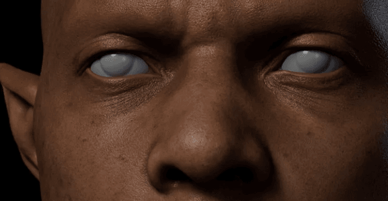
I find it really challenging to sculpt the stone texture of a person. I thought about many complex techniques, but in the end, I realized that simplicity was the key. I approached the sculpture by working on each part separately, starting with the face. I searched for a lot of references, mostly of elderly men, as well as some images of muscles and bones.

Since I wanted to create a stone statue of a person, capturing the subject's characteristics was essential. I pushed down the center of his forehead to give him a serious look. I made each facial feature three-dimensional, and since he appeared to be older, I carved deeper eye sockets and more pronounced cheekbones. The fabric carving was also quite challenging, but after studying and practicing, I got much better at it.

Sculpting high-poly model 1

Sculpting high-poly model 2

Sculpting high-poly model

Stone and wood: In this part, the team encountered some issues. Specifically, the wood texture appeared unnatural with no variation, and in some cases, the wood grain was even at an angle. Meanwhile, the stone was carved too softly without any layers. The best approach to solve these problems is to observe the small details that we often overlook in daily life, and then be more careful and patient when sculpting. It's essential to consider the intrinsic characteristics of the object and avoid over-sculpting just for the sake of it.

Sculpting small objects

Sculpting small objects

Pillar pattern: With the guidance of our teacher, we learned to use grayscale images to create some decorative effects. By using the correct method, we were able to save a lot of time in the project.

Pillar pattern

Pillar pattern

High-poly scene

High-poly scene

4. Making Low-poly Model

For irregular models such as figurines, eagles, and skulls, we exported their high-poly models and imported them into TopoGun for retopology. The topology was manually sketched using high-poly models, and followed the structure points while maintaining low face counts. Whenever possible, the convex structures were topologized, while small details, such as dents and damage sites, were achieved using normal maps instead of actual topology. It is important to follow the original structure when doing topology! Due to our lack of experience, we ran into various problems during the topology process, but we were gradually progressing. Regular objects were created by adding and subtracting lines from mid-poly models in the early stages.

Topology Model

Topology model

After completing the low-poly models, it was time to split the UV maps. This raised the question of how many textures and what size should be used. Since this was a personal project, we standardized our texture size to 1 m/512 pixels. We aimed to maintain consistent pixel density throughout the entire scene. For the figurines, I used four 4096 pixel textures, while over 30 textures were used for the whole scene. If any member failed to organize the files properly, it would cause difficulties during integration. Therefore, it is crucial to adhere to the standards when submitting the files.

split the UV maps

Next was time to bake the normal map. We chose to use Marmoset Toolbag for baking the normal map. Because the topology of the models was already completely matched during the process, there was no need to match the high- and low- poly models again. However, for regular models, the matching process should be done in 3ds Max. Then, separate the high- and low-poly parts and group them before importing them into Marmoset Toolbag for baking.

Marmoset Toolbag makes it convenient to manually edit some flawed normal maps. During baking, we make sure that the wrapper completely wraps around the high-poly models. If the normal map has minor issues, they can be fixed in Photoshop. However, if there are major problems, it's necessary to backtrack and search for the reason, such as whether a smooth group was separated but the UV wasn't disconnected.

5. Making Material

Our approach to material creation is to first identify the object's color and texture, create its volume, add textures, and finally add details. To maintain a consistent material tone across the entire scene, we had one student create the base materials, establish the tone, and then export intelligent material balls for others to use. They could then add texture details that suited their own model structures based on the established tone.

Effective material creation process requires collaboration and communication; working in isolation and obsessing over individual model details while neglecting overall effects and tonal consistency is problematic.

Layering materials can create more intricate effects, so it is advisable to experiment with different combinations.

Making Material 1

Making Material 2

Making Material 3

Making Material 4

6. Rendering

We rendered using Unreal Engine 4. As we were new to the software, the team leader learned the software while attempting to adjust the visual effects. When importing files from 3ds Max to Unreal Engine 4, the team leader discovered an Unreal Engine official importer plugin called Unreal Datasmith, which greatly facilitated our work progress by allowing us to import all models into Unreal Engine 4.

The most significant challenge we faced during resource integration was not knowing which map corresponded to which model. Therefore, the team leader requested that each team member partition their own models and maps. For example, if two items shared a map, the map and items had to be screenshotted together, with the size of the map marked. Later we found out that material effects were inconsistent - they were either too dark or too bright, perhaps due to lighting issues.

In Unreal Engine, the team leader made detailed partitions for each person's model maps and material ball files. Different folders were given different colors, making it more efficient to organize and replace files.

Rendering 1

Rendering 2

Rendering 3

Conclusion

The above is our experience sharing of the entire production process. In conclusion, I would like to say that the process is more important than the outcome. Due to our lack of experience, there were significant differences between our work and our desired results. However, we gained much from this process. We learned about teamwork, gained technical knowledge, and understood many life lessons. The scene project production process was a valuable lesson in our lives. Therefore, I just want to say that we are all the best!

Source: Thepoly

Welcome to join us

render farm free trial

Recommended reading


How to Render High-quality Images in Blender

2020-03-09


Top 9 Best And Free Blender Render Farms of 2023

2022-05-09


Revealing the Techniques Behind the Production of Jibaro "Love, Death & Robots", Which Took Two Years to Draw the Storyboard

2022-06-10


How to Render Large Scenes with Redshift in Cinema 4D

2019-10-15


Top 10 Free And Best Cloud Rendering Services in 2023

2022-06-24


Top 8 After Effects Render Farm Recommended of 2023

2022-07-07


How to Reduce Noise in Corona Renderer - Corona Denoising

2019-05-15


Arnold\ V-Ray\ Octane\ Conora\ RedShift, Which Is The Best 3D Renderer?

2019-04-15


Partners

Interested

Learn How to Make a Handheld Fan in 3D
Today, Fox Renderfarm, the industry's leading cloud rendering service provider and render farm, will bring you a 3D tutorial that explains how to make a handheld fan. Let's get started right now.1. First import the image, use the straight line tool to draw the length of the handle, then use the rotational molding tool to create the handle and add a cover.!1!22. Generate a rectangle using the center point, adjust it to the appropriate size, and then generate a circular runway. At this point, use the fitting tool to get the appropriate shape.!3!43. Select the circular runway that was just generated, hold down Shift to extrude the faces on both sides and add a cover, then use the shell tool to shell both sides.!5!64. Copy the inner edge line of the shell, extrude the face and add the cover, pull off the inner face to keep only the outer side, and then chamfer to generate the outer layer of the shell that needs to be hollowed out.!7!85. Use curves to draw the edge shape of the connecting axis, then use rotational molding to generate the surface, and then add the cover to generate the solid.!96. Connect the rectangle diagonal, use the diagonal to generate a round tube, and adjust the angle and thickness of the tube so that the angle and thickness of the tube match the reference picture.!10!117. Draw a diagonal line again and use the Line Array tool to array along this line, where the number of arrays is 18.!128. Use the object intersection line function to select the round tube and the shell to be hollowed out, determine whether the position matches by the object intersection line, adjust the position and then cut to get the hollowed out object.!13!149. Use the Rectangle tool to generate a runway circle, adjust it to the right size, then cut and combine it with the hollow object and offset it inward to get the solid. The same can be done for the outer runway circle, here you need to make a copy of the hollow object for backup.!15!1610. Use the mirror tool to mirror the hollowed-out model made in the previous step to the back, then use the method in the fourth step to get an unhollowed-out shell, generate a rounded rectangle and cut it according to the second reference picture, then use the combination tool to combine, and finally offset the surface to get the solid.!17!18!19!20!2111. Use a rectangle to frame the size of the button, then use a straight line to connect the midpoint of the rectangle, next use the center point tool to generate a circle, and squeeze the circle to the right size and adjust the height of the button.!22!23!2412. Split the button and the handle for spare, and then chamfer the top of the handle for the next step.!25!2613. For the base, again using the rotational molding tool. First draw the edge shape using curves, then rotate the shape and cap it to create a solid.!27!28!2914. Now perform the Boolean split between the handle and the base, then detach the surface. Next, copy the edge line, move the inner circle downwards, use the double rail sweep to generate the surface and combine it to obtain the base shape.!30!31!3215. Use the center point circle and rectangle tools to generate the button and indicator light shapes on the handle, extrude the solid and then perform a boolean split with the handle to get the handle shape and the indicator light.!33!34!3516. Use the Rectangle to create the runway circle and rotate it 45° to get the "x" below, then use the Trim tool to trim off the excess lines and combine them. After extruding the surface, use the Boolean split tool to split it to get the "x" icon.!36!37!3817. Now create the circular texture on the button. First abstract the structure line to get a button-sized circle, then generate a circle solid at the circle node, and use the Array Along Curve tool to make an array. Arrange the five columns in sequence according to the image and mirror them to get the desired texture. Finally, we use Boolean split to get the button shape.!39!40!41!4218. Chamfer the intersection of the button and the handle, and chamfer the intersection of the handle and the base.!43!4419. Use the curve to draw the fan shape, then use the XN tool to generate the surface, and array along the center point. The number of arrays here is 5. Adjust the fan blade position and extrude the fan blade solid.!45!4620. Check the model and chamfer it to complete the model.!4721. The next step is to render the product. First, divide the product into four layers, one for the orange object, one for the flesh-colored object, one for the metal connection, and one for the self-illumination. Then start rendering.!4822. First adjust the model position by aligning the model to the ground in the Advanced Options.!4923. Set the model materials to the model in turn. Note that you need to turn down the metallic shine of the metal joints in order to get a frosted look.!5024. Adjust the self-luminous material on the handle to the right intensity in accordance with the light, and choose white as the color.!5125. Set the setting options in the image to Press Exposure, High Contrast, and Photography.!52!5326. Change the background color in the environment settings. Use the straw tool to absorb the image color, turn down the brightness of one light in the HDR editor, hit the light on the hollow surface, adjust the shape of the light to rectangle, and then hit a main light on the left side of the product to make a shadow appear on the right side.!5427. Adjust the object position in the camera, lock the camera, and finish the rendering.!55!56Source: YBW
More
2023-06-02
How to Use VFace and Make Effects in Arnold?
In this article, Fox Renderfarm, the CG industry's leading cloud rendering service provider and render farm, will share with you how to use VFace and how to restore effects in the Arnold renderer. The author is CaoJiajun.Firstly I purchased some VFace materials from the official website to get the following files.!VFace materials!VFace materials!VFace materials!VFace materialsWe will mainly use the above files for this sharing, they are our main materials to make high quality details of the face. VFace provides 2 types of facial models, one for the head with open eyes and one for the head with closed eyes, choose one of them according to your needs. If you are doing a model that needs to be animated with expressions in post, I would recommend choosing the model with closed eyes, as the open eyes model will cause the eyelids to stretch when you do the blink animation. You don't need to worry about this for still-frame work.Let's start with the production process. It's actually very simple, wrap your own model with a VFace model through Wrap or Zwrap, then pass the map and finally render it in Maya or other 3D software. The process is simple but there will be a lot of things that need to be taken care of in there otherwise the facial details will not be rendered correctly. 1 Model CleaningFirst we need to load the model provided by VFace into ZBrush and match it to our sculpted model.Then you can head into Zwrap or Wrap for wrapping.Lastly, the wrapped model is imported into ZBrush to replace the VFace model.In ZBrush we use the Project brush to match the face of the wrapped model more precisely to our own sculpted model, once matched you will have a model that matches your sculpted model perfectly, at this point we can go into Mari for the map transfer.!Model Cleaning!Model Cleaning 2 Using Mari to Transfer the MapIn Mari we first set up the project, import our own sculpted model or the wrapped and matched XYZ model, then remove the other channels in the Channels and keep only the Basecolor channel, and we can customize the channels as we wish.!set up the project!set up the projectWhat we see now is how the model looks when imported into Mari. At this point we need to set the custom channels DIFF\DISP\UNITY\ to import the VFace map.Firstly, the DIFF channel is set at the original size of 16k and the Depth is set at 16bit (later on there can be more color depth control and of course it can be set to 8bit). The key point is that when the color depth is set to 16bit or 32bit, the color space needs to be set to linear and 8bit to srgb.Keep the size of displacement map at 16k. I recommend setting the Depth to 32bit, as you will get more detail of displacement, and keep the color space linear, with Scalar Data ticked (as the displacement map is a color map with 3 channels of RGB, you need to keep the greyscale data).The blend map settings are the same as the color map, but Scalar Data also needs to be ticked (this map is used as a color mask for toning or as a weighting mask).!Configuring channels!Configuring channels!Configuring channels!Configuring channels!Configuring channels!Configuring channelsNext we can use the object panel to append our own model in preparation for the transfer of the map.!transfer map!transfer mapRight-click on any channel and select the Transfer command in the pop-up menu to bring up the menu for transferring the map.In the transfer menu select the channel which needs to be transferred in the first step, set the transfer object in the second step, click on the arrow in the third step, set the size in the fourth step and finally click on the ok button.I generally recommend passing one channel at a time as it is very slow and takes a long time to wait. For size I usually choose 4k for color, 8k for displacement and 4k for mixing channels. This step requires a lot of patience!!VFace original effect!VFace original effectVFace original effect!The effect after transferThe effect after transfer!transfer settings!transfer settings!transfer settingsAfter the transfer we can export the map. The export map settings are shown in the figure. We need to pay attention to the color space setting (in the red box). The color space of the color channel is set to linear and should also be set to linear when exporting. The export of displacement and hybrid maps is a bit more unusual, as we set the color space to linear when creating the channel, but the export needs to be set to srgb, as both the displacement and hybrid maps are a combination of the 3 channels R,G,B to form a color map. Finally click the export button and it's done.!VFace original color effectVFace original color effect!Color effects after exportingColor effects after exporting!VFace original displacementVFace original displacement!Effect after exportEffect after exportIn short, your output map needs to be the same color as the map provided by VFace, either too bright or too dark is an error. 3 Arnold Rendering!Default settings!Default settingsDefault settingsAt this point we can go to Maya and render the VFace map we have created (we won't go into the lighting environment and materials here, we will focus on the link to the replacement map). First we import the passed VFace map and render it by default to see what we get. Obviously we get an ugly result, so how to set it to get it right?!Linking method for displacement map!Linking method for displacement mapHere we add an aisubtract node (which you can interpret as a subtraction or exclusion node), because the default median value of VFace is 0.5 and arnold prefers a replacement map with a median value of 0. So we enter the VFace color into input1 and change the color of input2 to a luminance value of 0.5. This is equivalent to subtracting the 0.5 luminance info from the default 0.5 median luminance of VFace, and we get a displacement with a median value of 0.!Median value 0.5Median value 0.5!Median value 0Median value 0!add aimultply node!add aimultply nodeAfter setting the median we can add an aimultply node. This node can be interpreted as a multiplyDivide node, which has the same function as Maya's own multiplyDivide node and controls the overall strength of the VFace displacement. We can output the color of the aisubract node to the input1 node of aimultply and adjust the overall strength of the detail displacement of VFace by using the black, grey and white of input2 (any value multiplied by 1 equals 1, any value multiplied by 0 equals 0, all the colors we can see in the computer are actually numbers to the computer. We can change the value and thus the strength of the map by simple mathematical calculations, once we know this we can see why we use the multiplyDivide node to control the strength of the displacement).!nodes settings!nodes settingsNext we add an ailayerRgba node. The R, G and B channels of the aimultipy are connected to the R channels of input1, 2 and 3 of ailayerRgba, and through the mix attribute of this node we can control the intensity of the displacement of each of the three VFace channels (R, G and B), and after a series of settings we can get a correct and controlled rendering of the VFace displacement.!VFace-dispVFace-disp!ZBrush-dispZBrush-disp!VFace+ZBrush DispVFace+ZBrush disp!ZBrush Export Displacement Settings!ZBrush Export Displacement SettingsZBrush Export Displacement SettingsAlthough we have a correct and controlled VFace displacement result, it does not combine with the displacement we sculpted in Zbrush and we need to find a way to combine the two to get our final displacement effect.Here I used the aiAdd node to add the two displacement maps together to get our VFace displacement + ZBrush displacement effect (of course you can also use Maya's plusMinus node).It doesn't matter how many displacement map elements you have (such as the scar on the face, etc.), you can structure them through the aiAdd node to get a composite displacement effect. The advantage of making it this way is that you can adjust the strength and weakness of each displacement channel at any time, without having to import and export them in different software. It is a very standard linear process approach.!Default effectDefault effect!After color correctionAfter color correctionFinally we apply the passed color to the subsurface color, and by default we get a very dark color mapping, which is not wrong. The VFace default model will be the same color. We can correct the skin color by using the hue, saturation and lightness of the colourCorrect node. This is why I choose 16bit colors to bake with, so I can get more control over the colors and get a correct result after color correction (of course the current result is just a rough mapping, we can still do deeper work on the map to get a better result).As a powerful render farm offering arnold cloud rendering services, Fox Renderfarm hopes this article can give you some help.Source: Thepoly
More
2023-06-16
Create a Next-Generation Scene "Things From The Outside" with 3ds Max
In this article, Fox Renderfarm, the CG industry's leading cloud rendering service provider and render farm, shares a collaborative 3D scene tutorial, "Things From The Outside," produced by a team of 3D art and design students.This was the first time they used ZBrush in their production process, so they encountered a lot of difficulties and challenges. They chose to make a scene of an interior temple that was more complex in terms of sculpting but with relatively single materials, with the main purpose of increasing their ZBrush proficiency.The final result:!final result 1!final result 2 Production Flow Analysis of Original PaintingsThe first thing we did was to assign tasks. One person built the rough model, showed everything in the original painting with simple geometry, and then adjusted the scale. Then, based on the original painting, we analyzed the assets and divided the job. We assigned the tasks of each component of the original painting to each member of the group.!assign tasksWhen building the rough model, put the camera at the same angle as the original painting as much as possible. Building a rough model is about accurate proportions, so be sure to carefully find the right proportional relationship between each object and reproduce it. Making Mid-poly ModelWe used Substance Painter to create materials and divided the models that require sculpting in ZBrush into two categories: heavy and light sculpting. For some stones, we used 3ds Max to create a low-poly model before sculpting details in ZBrush. For irregular objects such as the white cube in the middle, we also used 3ds Max to build a rough model before creating a high-poly model in ZBrush.!Making Mid-poly Model Making High-poly ModelAs shown in the above figure, two processes for creating high-poly models are demonstrated. The top stone model only requires sculpting of cracks and damage, while the bottom statue requires full sculpting. The process of creating high-poly models mainly involves refining rough blocky polyhedrons into objects that truly resemble the objects in the original painting. We encountered many difficulties during this process, but through continuous practice, we have improved our proficiency in using ZBrush.In my opinion, the most important thing in stone sculpting is to express the "mottled" traces of the stone. As a stone in the natural world, it must have been weathered by wind and rain, so a smooth stone will definitely give people an unnatural feeling.The method I used is the sculpting technique taught by my teacher. First, using the TrimSmoothBorder brush with a square alpha on the rough shaping can easily create a mottled surface. After that, reducing the brush size for detailing can result in a very "mottled" stone surface.As for human body sculptures, which are closely related to the human body, it was very difficult for us who have no background in art. We received several help from our teacher during the process, so that our "zero-based" group could sculpt a human body statue successfully. !Making High-poly Model Making Low-poly ModelFor us, the creation of low-poly models is also a new topic in creating a next-generation scene because it requires topology. I think topology is a very demanding task because, besides reducing the number of faces as much as possible, the corresponding model also needs to be planned, which means considering which high-poly models need to be topologized into a low-poly one. Topologizing multiple high-poly models onto a low-poly one can not only save the resources of a model but also reduce unnecessary time waste during the later UV unwrapping and material making processes. There were two methods for topology: ZRemesher and Topgun, with the former being automatic and the latter being manual. However, according to our teacher, it was basically impossible for real company projects to use ZRemesher because automatic topology does not meet wiring standards. Therefore, for this scene project, we chose manual topology.After topology was completed, it was time to unwrap UV. However, since we were working together and dividing the work, there may be inconsistency in the size of UVs. Therefore, before unwrapping UVs, an important task needed to be completed which was to determine the pixel accuracy. By using the same pixel accuracy, it was possible to determine how many UV maps each team member needed for their respective creations, thereby ensuring consistent pixel accuracy throughout the entire scene.Thanks to the powerful real-time preview function of Marmoset Toolbag, all the models in this project were baked in it. If there were any normal distortions, they could be modified in real-time, which saved a lot of time checking for normal errors. Also, since many models were created through topology, a lot of time was saved in matching the high and low-poly model.!Making Low-poly Model Making MapsBefore making maps, our teacher told us that if there were a large number of models in the scene that had similar or identical materials, we could first create a basic smart material and then distribute it to team members for modification based on this material. This would help avoid situations where the overall color of the materials was inconsistent during final integration.The materials used to create this natural environment can be roughly divided into three aspects: basic materials, volume relationship, and details. The basic materials were uniform for all the group members, so what really needed to be worked on were the two plates of volume relationship and details.Regarding the volume relationship, it is better to highlight changes in light and shadow, so that the whole object does not look very flat. In terms of details, as the original scene is in a perennial moisture environment, so that there would be some moss in the location near the ground, and then the overall performance would be a little wet. In short, to try to meet the characteristics of the scene in the original painting.!Making Maps 1!Making Maps 2!Making Maps 3!Making Maps 4!Making Maps 5 RenderingWe used Marmoset Toolbag to create the final rendered image. Marmoset Toolbag 4.03 has added support for ray tracing, making the lighting of the scene look very beautiful. Therefore, at the beginning, we did not consider additional lighting and relied too much on this feature. As a result, the entire scene rendered with large areas of dead black, while the bright parts were not emphasized. The reasons for this are firstly, the light and shadow relationships were not displayed clearly; secondly, cold light sources were not used to handle the dead black parts in the dark areas; thirdly, there were a large number of candles in the scene, but the candlelight was not simply completed by self-illumination and required additional fill light to achieve the desired effect. Of course, there may be many other problems as well. Finally, with the help of the teacher, our scene "regained life". The following two images can be seen for comparison.!Rendering!final result 1 ConclusionThe above is the process and experience sharing of our group in making the next-generation 3D scenes. We have learned valuable things about collaboration and hope that these experiences can give you some help and encouragement.Source: Thepoly
More
2023-06-08
  • Foxrenderfarm

    Powerful Render Farm Service

  • TPN
  • TPN

    Business Consulting

    Global Agent Contact:Gordon Shaw

    Email: gordon@foxrenderfarm.com

    Marketing Contact: Rachel Chen

    Email: rachel@foxrenderfarm.com

    Connect with Us

Fackbook Customer Reviews