20% Bonus On your First Rechargeclose

¿Qué Son la Topología y la Retopología de los Modelos 3D?

Qué Son la Topología y la Retopología de los Modelos 3D-2

Introducción

En este artículo, el mejor proveedor de servicios de granjas de renderización y renderizado en la nube en la CPU y en la GPU, Fox Renderfarm, le dirá qué son las topologías y las retopologías de los modelos 3D y cómo retopologizar un modelo en C4D.

Cuando utiliza un programa 3D para modelar, cada uno tiene sus métodos y sus procesos, y la construcción de un mismo modelo variará de una persona a otra. Pero, ¿qué hace que un modelo sea bueno? Si un modelo está mal estructurado, ¿cómo optimizarlo? Estos problemas tienen que ver con la topología y la retopología del modelo. Con estas preguntas, veamos a qué problemas debemos prestar atención en el proceso de modelización.

Qué Son la Topología y la Retopología de los Modelos 3D-1

¿Qué Son la Topología y la Retopología?

La topología tradicional es un tema relacionado con la geometría matemática, pero aquí tratamos los conceptos de topología relacionados con el modelado 3D. Ahora, usted entenderá qué es la topología y luego, la retopología.

•Topología

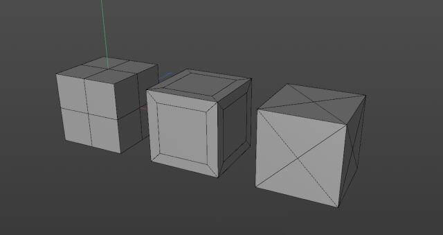
Quizás usted conoce que un modelo se representa en un programa 3D mediante una serie de superficies combinadas en diferentes ángulos. En mi opinión, la topología del modelado 3D es la distribución estructural de las superficies de un modelo, que es el cableado. Hay muchas formas de combinar superficies cuando se trata de representar y hacer un modelo 3D. Por ejemplo, mire el cubo de abajo, aunque la distribución de las superficies es inconsistente, la apariencia es exactamente la misma.

Qué Son la Topología y la Retopología de los Modelos 3D-2

Cada modelo tiene su propia topología. Algunos son modelos industriales exportados por programas de diseño industrial, como ProE y SolidWorks; otros están hechos por escaneado u otro tipo de ingeniería inversa; otros tienen el formato de modelo común, como *.obj, *.fbx, etc. que exportan distintos software 3D. Aquí viene un problema: Aunque se trate del mismo modelo, la topología generada de diferentes maneras, a veces, puede generar problemas en la posterior animación y en el reprocesado.

•Retopología

Una vez entendida la topología, la retopología es sencilla. Se trata de reconstruir y representar el mismo modelo, utilizando una topología mejor: Una distribución más adecuada de las superficies.

Qué Son la Topología y la Retopología de los Modelos 3D-3

Cuando retopologiza un modelo, prestará más atención a la utilización de un número y a un tamaño adecuado de las superficies para representarlo. Y si necesita hacer animaciones a nivel de puntos (animación del cuerpo del personaje, tela, etc.), deberá prestar más atención a la construcción de algunas estructuras de los anillos y los bucles, para que pueda hacer frente a los problemas en las animaciones (como la colisión del modelo, el estiramiento excesivo, etc.) producidas después de la extrusión y el estiramiento de las superficies.

Qué Son la Topología y la Retopología de los Modelos 3D-4

¿Qué Es una Buena Topología?

En primer lugar, para hacer un buen modelo hay que intentar evitar las superficies triangulares y las superficies n-gon conectadas por más de 5 bordes, e intentar no hacer polos con más de 5 bordes en posiciones importantes. De lo contrario, pueden aparecer superficies cruzadas o efectos poco suaves en estos lugares al realizar animaciones posteriores a nivel de puntos. Por ejemplo, en los modelos diseñados con programa industrial, hay muchas superficies triangulares después de convertir el formato, y será problemático crear efectos de biselado o añadir subdivisiones para estos bordes.

Qué Son la Topología y la Retopología de los Modelos 3D-5

En segundo lugar, un buen modelo debe tener un buen flujo de bordes, que no sólo es conveniente para la selección, sino que también ofrece una buena tensión durante la producción de la animación posterior.

Qué Son la Topología y la Retopología de los Modelos 3D-6

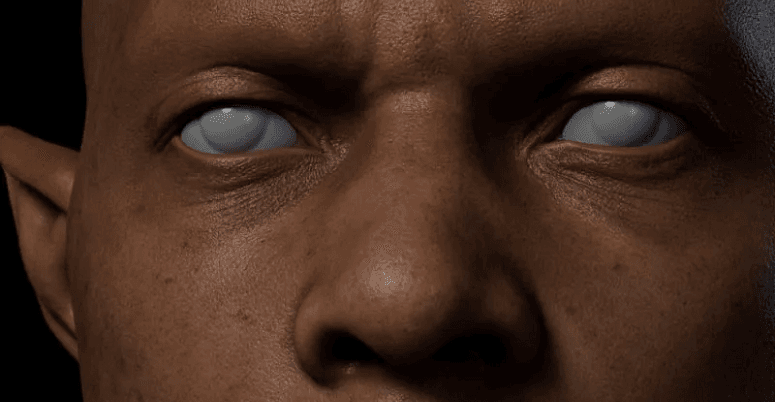
Algunas posiciones que deben animarse, como los ojos y la boca, deben modelarse con estructuras adecuadas y superficies suficientes para soportar los detalles de la animación.

Qué Son la Topología y la Retopología de los Modelos 3D-7

Qué Son la Topología y la Retopología de los Modelos 3D-8

¿Cuáles Son las Ventajas de la Retopología?

•Una buena topología puede mejorar la animación

Los modelos con estructuras razonables mostrarán un mejor modelado cuando se aprieten y deformen. Como los tres cubos con diferentes topologías que se muestran a continuación, algunas de sus superficies se rasgarán después de que se retuerzan hasta cierto grado.

Qué Son la Topología y la Retopología de los Modelos 3D-9

•Los modelos con buena topología se volverán a trabajar de manera más eficiente

Para estos modelos, cuando desee añadirle biseles o añadirle algunos detalles, podrá modificar rápidamente una parte específica de la superficie. Sin embargo, para los modelos con un cableado insatisfecho, sólo podrá añadir detalles aumentando de nuevo la distribución de las líneas de modificación, lo que resultará ineficaz para algunas estructuras complejas.

Qué Son la Topología y la Retopología de los Modelos 3D-10

•La retopología permite mapear más rápidamente

Para la producción de algunos mapeados, es necesario el estiramiento de UV. Si la densidad de las distintas zonas del modelo es muy diferente, o si hay tanto superficies triangulares como N-gons, hará que nuestro trabajo sea muy tedioso. Así que, después de la retopología, el modelo puede hacer que la producción y el rendimiento del mapeo de los materiales se vuelvan más eficaces.

Qué Son la Topología y la Retopología de los Modelos 3D-11

¿Cuáles Son las Formas de Retopología en C4D?

No hay muchas maneras de retopología en C4D, pero por lo general, utilizan la función de retopología de otro programa para mejorar el modelado. A continuación, verá 3 métodos de retopología.

•Rehacer algunas partes del modelo

Para algunas partes con estructuras simples, se puede hacer directamente a través de la geometría, y luego, conectar estas partes al modelo.

Qué Son la Topología y la Retopología de los Modelos 3D-12

Para algunas superficies, se puede utilizar "shrink wrap" y "polypaint" para retopologizar partes de la estructura. Por ejemplo, utilice el retractilado para ajustar algunas superficies distribuidas uniformemente al modelo, y después optimice y combine la estructura.

Qué Son la Topología y la Retopología de los Modelos 3D-13

•Utilización de objetos de volumen

En la versión posterior a R20, el uso de los objetos de volumen puede generar directamente un modelo con biseles relativamente uniforme, pero no hay mucho espacio para la manipulación, y a veces, los bordes no son ideales. Y si quiere más detalles, tiene que producir más modelos de superficie.

Qué Son la Topología y la Retopología de los Modelos 3D-14

•Usar QuadRemesher

Además de los dos métodos anteriores, también puede utilizar el complemento QuadRemesher para la retopología. Anteriormente, para este complemento, el desarrollador sólo había lanzado y probado la versión aplicada a Maya y 3ds Max. Recientemente, por fin ha salido la versión para C4D. Puedo decir que C4D no tenía un complemento de retopología fácil de usar antes, por lo que el lanzamiento de QuadRemesher permite ahorrar más tiempo. Su uso también es muy sencillo. Sólo hay que ajustar el número de superficies generadas, el tamaño y la densidad, y se puede obtener directamente un modelo ideal.

Qué Son la Topología y la Retopología de los Modelos 3D-15

Conclusión

La retopología puede ayudar a obtener un modelo más conforme, pero la forma de construir y procesar un modelo depende de sus necesidades de producción. Este es un buen artículo guía para que usted aprenda más: Tutorial de Modelado 3D: Abanico de mano. Si desea crear su trabajo utilizando sólo la forma del modelo, a continuación, sólo puede crear la forma que se adapte a las necesidades. Si desea hacer mapeo, animaciones y otros para el modelo, entonces usted debe agregar líneas adecuadamente de acuerdo a los requerimientos de la animación. La estructura del modelo puede mejorar la eficiencia para la etapa posterior.

Después de construir el modelo, si no está muy satisfecho con el efecto del renderizado C4D, puede buscar una granja de renderizado en la nube como Fox Renderfarm para ayudarle a renderizar. ¡Espero que este artículo le haya ayudado!

Interested

How to Create the Entrance of 'For Honor'
The leading cloud rendering service provider and render farm in the CG industry, Fox Renderfarm, will show you in this post a scene inside "For Honor," the Entrance, created by a student who is learning 3D modeling. The creator completed this work over a period of four weeks by solving problems and challenges with the help of his/her teacher and his/her own efforts. This article is a summary of his/her experience in the creation of this scene.Final result:Analyzing Concept Art &x26; Building Rough ModelsThis is a case of the PBR workflow, specifically utilizing 3ds Max for low-poly modeling, ZBrush for high-poly sculpting, TopoGun for retopology, Substance Painter and Photoshop for texture, and ultimately rendering with Marmoset Toolbag 4.To ensure production progress, in the early stages, the scene was initially constructed in 3ds Max based on the concept art as a large-scale reference for proportions, and then the actual production process began.Rough modelMaking Mid-poly ModelsHouse Structure: serving as the foundation of the scene framework. The house was divided into several parts for construction, including the roof, walls, floor, door frames, steps, and two side stone platforms. Through analyzing the concept art, it was determined that the stone walls and roof tiles employ a repeating texture pattern, which was subsequently applied throughout the scene.The scene props included stone lion statues, lanterns, ropes of hanging tassels, and more. Among them, the stone statues, steps, and several wooden elements were sculpted using ZBrush.The process of creating the mid-poly model involved continuously refining and adding more intricate details based on the rough model. It was important to analyze which models require sculpting and retopology during the initial stages of production, and which models could be reduced in detail to serve as the low-poly model. Conducting this analysis early on significantly improved efficiency in the production process.Mid-poly modelMaking High-poly ModelsThe high-poly modeling stage was relatively intense, involving numerous wooden doors, plaques, walls, as well as stone steps and statues. However, the task became less laborious when it came to identical wooden boards in the scene, as they could be easily adjusted and reused.Statue sculpting:Since the only element in this scene that required complete sculpting was the stone lion, I decided to challenge and improve my sculpting skills by starting from a sphere. After several days of sculpting, I began to see some progress. Then, with guidance from my teacher, I delved deeper into proportions, structure, and finer details.Props sculpting:The wooden boards, during the sculpting process, were meticulously sculpted stroke by stroke to enhance the texture and bring out the grain. Additionally, props like stone steps were also carved.Afterward, the UV unwrapping and baking process followed.Making Low-poly ModelsIn the early stages, we conducted an analysis of the assets. Among them, only the stone lion required retopology, while the remaining props could be obtained through reducing the mesh of mid-poly models.Overall, retopologizing the low-poly model is a relatively simple but patient task. There are several points to consider during the process: 1. Controlling the polygon count of the model. 2. Planning the mesh topology in a logical manner and determining whether certain details need to be retopologized. 3. Evaluating the density of the mesh topology for proper distribution.During the low-poly retopology stage, we encountered few difficulties. We followed a standard of 1m³/512 pixels to create the textures and planned them accordingly based on the predetermined pixel density. Then, we proceeded with UV unwrapping and layout. Throughout this process, we encountered issues such as seams appearing and models turning black. Eventually, we identified the problems as certain areas of the model lacking smooth group separation in the UVs and flipped normals. When placing the UVs, it is important to fully utilize the UV space to avoid wasting resources. Additionally, we needed to redo some of the UV work later on. It should be noted that in 3ds Max, when using automatic smoothing groups, it may not be apparent if the normals are flipped. Therefore, it is advisable to double-check after completing each section.Next was the normal map baking. We matched the high-poly and low-poly models in 3ds Max and ensured that there was some distance between all the models to avoid overlapping during the baking process. If any issues arose with the baked normals, we would repair them in Photoshop. Fortunately, there were no major problems throughout the entire baking process, so minor adjustments in Photoshop were sufficient.Low-poly modelMaking MaterialsI initially conducted material rendering for the sculpture and showed it to my teacher. However, the teacher pointed out some shortcomings. With guidance from the teacher, I gained a new understanding of material rendering. The key is to focus on volume first and then details. Volume here does not solely refer to the presence of volume under lighting conditions, but also the perception of volume even in the absence of lighting, relying only on colors. The addition of darker shades and textures further enhances the sense of volume in the model. Finally, sharpening was performed to make the details more prominent. By following this approach, the materials created would appear three-dimensional under lighting effects.RenderingAfter completing meticulous file organization, I standardized the naming of models, material spheres, and textures. This significantly reduced the workload when using Marmoset Toolbag 4. Once all the preparations were done, I began placing the models, setting up the lighting, adding special effects, and finally positioning the camera for rendering. During this process, a considerable amount of time was spent on lighting. The coordination between model materials and lighting never seemed to achieve the desired effect. However, with guidance from my teacher, I was able to improve the overall result.The above is our experience sharing the production process of the Entrance for the game "For Honor".Source: Thepoly
More
2023-09-28
Learn How to Make a Handheld Fan in 3D
Today, Fox Renderfarm, the industry's leading cloud rendering service provider and render farm, will bring you a 3D tutorial that explains how to make a handheld fan. Let's get started right now.First import the image, use the straight line tool to draw the length of the handle, then use the rotational molding tool to create the handle and add a cover.Generate a rectangle using the center point, adjust it to the appropriate size, and then generate a circular runway. At this point, use the fitting tool to get the appropriate shape.Select the circular runway that was just generated, hold down Shift to extrude the faces on both sides and add a cover, then use the shell tool to shell both sides.Copy the inner edge line of the shell, extrude the face and add the cover, pull off the inner face to keep only the outer side, and then chamfer to generate the outer layer of the shell that needs to be hollowed out.Use curves to draw the edge shape of the connecting axis, then use rotational molding to generate the surface, and then add the cover to generate the solid.Connect the rectangle diagonal, use the diagonal to generate a round tube, and adjust the angle and thickness of the tube so that the angle and thickness of the tube match the reference picture.Draw a diagonal line again and use the Line Array tool to array along this line, where the number of arrays is 18.Use the object intersection line function to select the round tube and the shell to be hollowed out, determine whether the position matches by the object intersection line, adjust the position and then cut to get the hollowed out object.Use the Rectangle tool to generate a runway circle, adjust it to the right size, then cut and combine it with the hollow object and offset it inward to get the solid. The same can be done for the outer runway circle, here you need to make a copy of the hollow object for backup.Use the mirror tool to mirror the hollowed-out model made in the previous step to the back, then use the method in the fourth step to get an unhollowed-out shell, generate a rounded rectangle and cut it according to the second reference picture, then use the combination tool to combine, and finally offset the surface to get the solid.Use a rectangle to frame the size of the button, then use a straight line to connect the midpoint of the rectangle, next use the center point tool to generate a circle, and squeeze the circle to the right size and adjust the height of the button.Split the button and the handle for spare, and then chamfer the top of the handle for the next step.For the base, again using the rotational molding tool. First draw the edge shape using curves, then rotate the shape and cap it to create a solid.Now perform the Boolean split between the handle and the base, then detach the surface. Next, copy the edge line, move the inner circle downwards, use the double rail sweep to generate the surface and combine it to obtain the base shape.Use the center point circle and rectangle tools to generate the button and indicator light shapes on the handle, extrude the solid and then perform a boolean split with the handle to get the handle shape and the indicator light.Use the Rectangle to create the runway circle and rotate it 45° to get the "x" below, then use the Trim tool to trim off the excess lines and combine them. After extruding the surface, use the Boolean split tool to split it to get the "x" icon.Now create the circular texture on the button. First abstract the structure line to get a button-sized circle, then generate a circle solid at the circle node, and use the Array Along Curve tool to make an array. Arrange the five columns in sequence according to the image and mirror them to get the desired texture. Finally, we use Boolean split to get the button shape.Chamfer the intersection of the button and the handle, and chamfer the intersection of the handle and the base.Use the curve to draw the fan shape, then use the XN tool to generate the surface, and array along the center point. The number of arrays here is 5. Adjust the fan blade position and extrude the fan blade solid.Check the model and chamfer it to complete the model.The next step is to render the product. First, divide the product into four layers, one for the orange object, one for the flesh-colored object, one for the metal connection, and one for the self-illumination. Then start rendering.First adjust the model position by aligning the model to the ground in the Advanced Options.Set the model materials to the model in turn. Note that you need to turn down the metallic shine of the metal joints in order to get a frosted look.Adjust the self-luminous material on the handle to the right intensity in accordance with the light, and choose white as the color.Set the setting options in the image to Press Exposure, High Contrast, and Photography.Change the background color in the environment settings. Use the straw tool to absorb the image color, turn down the brightness of one light in the HDR editor, hit the light on the hollow surface, adjust the shape of the light to rectangle, and then hit a main light on the left side of the product to make a shadow appear on the right side.Adjust the object position in the camera, lock the camera, and finish the rendering.Source: YBW
More
2023-07-20
How to Use VFace and Make Effects in Arnold?
In this article, Fox Renderfarm, the CG industry's leading cloud rendering service provider and render farm, will share with you how to use VFace and how to restore effects in the Arnold renderer. The author is CaoJiajun.Firstly I purchased some VFace materials from the official website to get the following files.We will mainly use the above files for this sharing, they are our main materials to make high quality details of the face. VFace provides 2 types of facial models, one for the head with open eyes and one for the head with closed eyes, choose one of them according to your needs. If you are doing a model that needs to be animated with expressions in post, I would recommend choosing the model with closed eyes, as the open eyes model will cause the eyelids to stretch when you do the blink animation. You don't need to worry about this for still-frame work.Let's start with the production process. It's actually very simple, wrap your own model with a VFace model through Wrap or Zwrap, then pass the map and finally render it in Maya or other 3D software. The process is simple but there will be a lot of things that need to be taken care of in there otherwise the facial details will not be rendered correctly.1 Model CleaningFirst we need to load the model provided by VFace into ZBrush and match it to our sculpted model.Then you can head into Zwrap or Wrap for wrapping.Lastly, the wrapped model is imported into ZBrush to replace the VFace model.In ZBrush we use the Project brush to match the face of the wrapped model more precisely to our own sculpted model, once matched you will have a model that matches your sculpted model perfectly, at this point we can go into Mari for the map transfer.2 Using Mari to Transfer the MapIn Mari we first set up the project, import our own sculpted model or the wrapped and matched XYZ model, then remove the other channels in the Channels and keep only the Basecolor channel, and we can customize the channels as we wish.What we see now is how the model looks when imported into Mari. At this point we need to set the custom channels DIFF\DISP\UNITY\ to import the VFace map.Firstly, the DIFF channel is set at the original size of 16k and the Depth is set at 16bit (later on there can be more color depth control and of course it can be set to 8bit). The key point is that when the color depth is set to 16bit or 32bit, the color space needs to be set to linear and 8bit to srgb.Keep the size of displacement map at 16k. I recommend setting the Depth to 32bit, as you will get more detail of displacement, and keep the color space linear, with Scalar Data ticked (as the displacement map is a color map with 3 channels of RGB, you need to keep the greyscale data).The blend map settings are the same as the color map, but Scalar Data also needs to be ticked (this map is used as a color mask for toning or as a weighting mask).Next we can use the object panel to append our own model in preparation for the transfer of the map.Right-click on any channel and select the Transfer command in the pop-up menu to bring up the menu for transferring the map.In the transfer menu select the channel which needs to be transferred in the first step, set the transfer object in the second step, click on the arrow in the third step, set the size in the fourth step and finally click on the ok button.I generally recommend passing one channel at a time as it is very slow and takes a long time to wait. For size I usually choose 4k for color, 8k for displacement and 4k for mixing channels. This step requires a lot of patience!VFace original effectThe effect after transferAfter the transfer we can export the map. The export map settings are shown in the figure. We need to pay attention to the color space setting (in the red box). The color space of the color channel is set to linear and should also be set to linear when exporting. The export of displacement and hybrid maps is a bit more unusual, as we set the color space to linear when creating the channel, but the export needs to be set to srgb, as both the displacement and hybrid maps are a combination of the 3 channels R,G,B to form a color map. Finally click the export button and it's done.VFace original color effectColor effects after exportingVFace original displacementEffect after exportIn short, your output map needs to be the same color as the map provided by VFace, either too bright or too dark is an error.3 Arnold RenderingDefault settingsAt this point we can go to Maya and render the VFace map we have created (we won't go into the lighting environment and materials here, we will focus on the link to the replacement map). First we import the passed VFace map and render it by default to see what we get. Obviously we get an ugly result, so how to set it to get it right?Here we add an aisubtract node (which you can interpret as a subtraction or exclusion node), because the default median value of VFace is 0.5 and arnold prefers a replacement map with a median value of 0. So we enter the VFace color into input1 and change the color of input2 to a luminance value of 0.5. This is equivalent to subtracting the 0.5 luminance info from the default 0.5 median luminance of VFace, and we get a displacement with a median value of 0.Median value 0.5Median value 0After setting the median we can add an aimultply node. This node can be interpreted as a multiplyDivide node, which has the same function as Maya's own multiplyDivide node and controls the overall strength of the VFace displacement. We can output the color of the aisubract node to the input1 node of aimultply and adjust the overall strength of the detail displacement of VFace by using the black, grey and white of input2 (any value multiplied by 1 equals 1, any value multiplied by 0 equals 0, all the colors we can see in the computer are actually numbers to the computer. We can change the value and thus the strength of the map by simple mathematical calculations, once we know this we can see why we use the multiplyDivide node to control the strength of the displacement).Next we add an ailayerRgba node. The R, G and B channels of the aimultipy are connected to the R channels of input1, 2 and 3 of ailayerRgba, and through the mix attribute of this node we can control the intensity of the displacement of each of the three VFace channels (R, G and B), and after a series of settings we can get a correct and controlled rendering of the VFace displacement.VFace-dispZBrush-dispVFace+ZBrush dispZBrush Export Displacement SettingsAlthough we have a correct and controlled VFace displacement result, it does not combine with the displacement we sculpted in Zbrush and we need to find a way to combine the two to get our final displacement effect.Here I used the aiAdd node to add the two displacement maps together to get our VFace displacement + ZBrush displacement effect (of course you can also use Maya's plusMinus node).It doesn't matter how many displacement map elements you have (such as the scar on the face, etc.), you can structure them through the aiAdd node to get a composite displacement effect. The advantage of making it this way is that you can adjust the strength and weakness of each displacement channel at any time, without having to import and export them in different software. It is a very standard linear process approach.Default effectAfter color correctionFinally we apply the passed color to the subsurface color, and by default we get a very dark color mapping, which is not wrong. The VFace default model will be the same color. We can correct the skin color by using the hue, saturation and lightness of the colourCorrect node. This is why I choose 16bit colors to bake with, so I can get more control over the colors and get a correct result after color correction (of course the current result is just a rough mapping, we can still do deeper work on the map to get a better result).As a powerful render farm offering arnold cloud rendering services, Fox Renderfarm hopes this article can give you some help.Source: Thepoly
More
2023-07-19
Business Consulting

Global Agent Contact: Evan Zhang

Email: evan.zhang@foxrenderfarm.com

Marketing Contact: Evan Liu

Email: evanliu@foxrenderfarm.com

Message Us:
Newsletter
Keep up with our latest software updates, special offers and events!
Copyright © 2025 FoxRenderfarm.com. All Rights Reserved.